VIRTUAL REALITY (DEVR)
Practical experience is very important in the construction of deep excavations. An inexperienced engineer may not be able to identify a potential problem in advanced because he or she does not have enough practical experience. For example, water seeping through retaining wall, insufficient preloading of bracing system, or inadequate excavating slope could cause extensive damage if the engineers cannot identify the problem and have the remedial work done in time.
Deep Excavation in Virtual Reality (DEVR) uses three-dimensional (3D) visualization and simulation to provide the users with a Virtual Environment (VE) of deep excavation site. The purpose of this program is to provide a VE that lets junior engineers or students of civil engineering experience "real" site conditions in deep excavation by computer simulation. DEVR efficiently gives engineers a "virtual" education that provides them with some of the practical experience that otherwise would take years to obtain.
Deep Excavation in Virtual Reality
Rapid urban growth has led to an increase in demand for prime real estate space. One solution to alleviate this problem is increasing the use of underground space for shopping malls, parking garages, and roads. A common and efficient construction method for utilizing such underground space is a deep excavation -- retaining wall construction followed by excavation and bracing system erection. Many big cities consist of numerous tall buildings supported by deep foundations with major underground utilities and tunnels. Because in deep excavation engineers must be aware of the effects of ground movements on adjacent structures, building protection, grouting treatment, and dewatering system are always involved. In a working site surrounded by high traffic-flow roads or buildings, it is difficult to find adequate space to store materials and equipment during excavation, therefore, a decking system is necessary during the process.
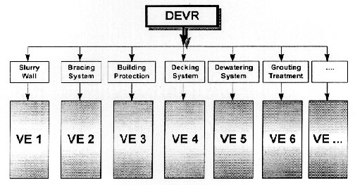
Depending on the site environment and underground conditions, slurry wall construction, building protection, a dewatering system, a bracing system and other related activities may be employed in a deep excavation construction. Implementing visualization of these construction into a virtual environment could be useful in conveying information about the construction process to junior engineers. Currently, the Deep Excavation in Virtual Reality (DEVR) program provides the 3D models of a bracing system and slurry walls, however, the same methodologies can be applied to other activities. The following sections discuss the methodologies and results for visualization in DEVR.
Background and Problems
One important construction project of the Six Year National Development Plan (1991-1997) in Taiwan was the Taipei Rapid Transit system (TRTS), located in Taipei, Taiwan, which was constructed to correct the increasingly serious transportation problem. The initial construction of the TRTS began in 1988. Among the civil contracts of TRTS, the Chung-Ho Line contract, also called CC560, has had the highest cost: its civil contract has reached US $670 million. The CC560 project was divided into four station contracts, CC275, CC276, CC277, CC278, and one tunnel contract in which the tunnels connect the four underground stations. Our program, DEVR, deals with the starting shaft, a pre-constructed shaft for erecting and launching a Tunnel Boring Machine (TBM), in the CC277 station.
The local construction industry in Taiwan did not have the capacity to build the entire Six Year National Development Plan. In fact, due to the inflation of the construction market and an insufficient number of professional engineers in Taiwan, a recent civil engineering graduate could immediately find employment as a site supervisor. Unfortunately, inexperienced junior engineers had difficulties in controlling the construction progress and in identifying or dealing with problems because they were not familiar with the site conditions.
A small number of construction corporations in Taiwan realized that professional training is important and have adopted such training, but most companies rejected additional training for their engineers because of the additional cost.
Objectives
In order to overcome the problem of insufficient practical experience, the DEVR program was developed in order that users may navigate in a virtual model of a deep excavation site and perceive the environment of construction via this model. There are two main objectives for this program: to develop 3D visualization and simulation of a deep excavation site for training and educational purposes, and to provide the methodologies for such purposes in both Virtual Reality (VR) and World Wide Web (WWW) applications.
3D Modeling and VR Application
"Virtual reality is a way for humans to visualize, manipulate and interact with computers and extremely complex data" [WTK 1993]. The visualization part refers to the computer generation of visual, auditory or other sensual outputs to the users of a world within the computer. This world may be a Computer-Aid Design (CAD) model, a scientific simulation, or a view into a database. Users can interact with the world and directly manipulate objects within the simulated world. Interaction with the virtual world is a critical test for a 'virtual reality', at least with near real time control of the viewpoint.
Generally speaking, two steps are required in order to accomplish the VR environment described above: the 3D modeling stage and the VR stage. In the 3D modeling stage, DEVR uses 3D Studio Version 3.0 as the 3D modeling package to create the virtual models of a deep excavation site with virtual slurry walls and the members of a bracing system. In the VR stage, the interaction between the users and the virtual environment is accomplished by importing the models into the World Tool Kit (WTK) Version 2.1. The WTK is a portable, cross-platform development system for virtual simulation and virtual reality applications that was developed by Sense8, Corporation.
WWW Application
The World Wide Web (WWW) can now be considered as the most powerful hypermedia available. In order to more efficiently tap the potential benefit of the internet, and to reach a wider audience, 3D animations and VR effects can be made available through the WWW. The homepage of the DEVR program has been successfully constructed on the WWW, thus permitting the program to be more broadly presented to the public, as well as enabling multiple users to interact in the VE simultaneously. The implementation of VR applications on the WWW is made possible by the Virtual Reality Modeling Language (VRML), that is further discussed in the Section titled "VR Application in WWW by VRML."
Introduction
The first step in creating a VE is to perform 3D modeling. This program uses 3D Studio Version 3.0 as the modeling software. The 3D Studio package is a 3D modeling, rendering, and animation tool from Autodesk, Inc. The software runs on a PC compatible platform. The 3D Studio software allows users to create three-dimensional, photo-realistic images for a variety of purposes.
Background of 3D Models
The 3D models in DEVR simulate the starting shaft of CC277. Station 277, an underground station which is divided into an entrance area and a station area, is one of the four stations on the Chung-Ho Line, TRTS (Taipei Rapid Transit System). The station area of CC277 includes the main box, one starting shaft, and one arriving shaft. The main box is where passengers board or exit the vehicle. The purpose of starting shaft construction is so that the TBM can be erected before the main box excavation, thereby permitting simultaneous tunnel boring and main box excavating. The main box and starting shaft are separated by partition walls, which are temporary retaining walls and that will be demolished during the main box excavation.
The objects in the virtual environment of this program are: H beams, slurry walls soils, and brackets. H beams can be categorized as wales, struts, corner struts, branch struts, blocking beams, soldier piles and pin piles. There are 15 blocks, representing 15 panels, of slurry walls and 5 blocks of soils.
Methodology
The most common objects in this program, and also the most complicated part of the modeling, are H beams. Because all the models should be scaled to the working drawings of CC277, each member has a different cross sectional area and length. To accomplish this modeling task, the following procedures were performed as described below.
(1) 2D Shaper
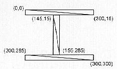
The initial screen that is set up in 3D Studio is the 3D Editor, which can be changed to the 2D Shaper by keyboard, or by using the mouse to select Program/2D Shaper in the toolbar. The 2D Shaper, which has functions that are similar to other drawing software, can create or edit two-dimensional splines. It can draw a variety of shapes and it provides select, delete, copy, and paste functions. A model of an H beam like 300X300Xl 0X 15, is created efficiently by using three rectangles to represent two flanges and one web in Create/Quad. The scales of these rectangles can be controlled by x and y coordinates (Figure 1).
After creating the actual scale of each dimension, the user chooses Shape/Assign and clicks on the three polygons. The purpose for assigning the polygons is to develop the length of the H beam in 3-D Lofter.
(2) 3D Lofter
In 2D Shaper, the user determines the cross section of an H beam, while the main function of 3D Lofter is to provide the path for it. The model will become a 3D model after this procedure is done. In fact, the 3D Lofter function not only provides a straight path for the length, but also allows multiple shapes in one path and changes the form of the path. All the models in DEVR require only the most basic functions of 3D Lofter. The following steps explain how to create a straight path for a shape.
(3) 3D Editor
The 3D Editor is the main prompt of 3D Studio and it is the first module that is displayed when starting 3D Studio. Users can create almost any object in the real world in the 3D Editor without using 2D Shaper and 3D Lofter. The basic functions can be categorized as the following types.
Create: 3D Studio provides several ways to create objects. The simplest method to create a new object is to choose ''Create/Object (Box LSphere, GSphere, Cylinder, Tube, Cone,... )." The dimensions of each object will be shown at the top of the screen by coordinates of the x, y. and z axes. For example, if the users want to create a box, the first step is to create a rectangle with the mouse. The length and width of this rectangle appear on the top screen. T hen the user can decide the height, also shown on the screen, of this box. A similar process is involved in creating a cone i.e., to determine the radius first and then the height.
Select: The purpose for selecting an object or objects is to modify or copy one or more objects easily. The object becomes deselected when it is selected twice.
Modify: Modifying the objects is the most time-consuming but easiest procedure in 3D Editor. DEVR uses this function only to modify objects and axes. "Modify/Object" in 3D Editor includes "Move," "Rotate " "2D scale," "3D Scale," "Skew," "Mirror," "Bend," and so on. The function of "Modify/Axis" contains "Place," "Align," etc.
Surface: When a 3D object is created in 3D Editor, the surface of this object is a default bitmap. Applying an appropriate bitmap to the surface of each object in 3D Editor involves three basic steps: choose material, assign material and map texture. The material library of 3D Studio provides more than one hundred bitmaps for the users to apply on objects. Users can choose one of them from the library at a time, and assign it on the objects. Due to the geometrical differences between the selected texture surfaces and object surfaces, mapping is not automatic and users have to perform the mapping process. Without these mapping coordinates, the bitmap properties, such as the diffuse, ambient, and specular, have no effect on the geometry when the model are rendered.
Lights: To intimate the real world in the VE, the light effect is very important. DEVR adopts one ambient light and one spot light. The intensity change of ambient light provides a VE in the day or night. And the purpose of the spot light in this program is to strengthen the brightness of the objects in the VE.
Cameras: There are seven static viewports in 3D Editor: top, bottom, left, right, front, back, and user's viewport. Note that in a real environment, seven static viewports would be insufficient. The function of a camera in the VE is like the human eyes in the real world. The cameras can move, roll or focus, just like the eyes. The VE will be helpful and realistic to the users only from the viewpoint of the camera.
Renderer: The result of the 3D models is obtained when the users render the models into an image file, which can be shown on the screen. The 3D Studio provides several image file types for the users to select: Graphic Interchange Format (*.GIF), TarGA (*.TGA), Tagged Image File Format (*.TIFF or *.TIF), BitMap (*.BMP), and Joint Photographic Experts Group (*.JPEG or *.JPG).
World Tool Kit (WTK)
To render virtual reality from the 3D objects created in 3D Studio, this program uses WorldToolKit (WTK) as the tool to accomplish the task. Through WTK, the graphic objects call acquire real-world properties and behavior. Users can control the virtual models through a variety of input sensors, such as a mouse, keyboard, spaceball, cyberglove, or a Head-Mounted stereoscopic Display (HMD). WTK is a library containing hundreds of C functions. The numerous and powerful functions enable users to custom design their own program using the C language.
WTK software has been developed for both a Windows (PC) and an SGI platform. The former is user friendly and readily accessible to general users, but the rendering speed and capacity is limited to models which are larger than 1 megabyte. In DEVR, the model is about 2.6 megabytes with 119 objects, 52900 vertices, and 99712 faces. Therefore, the WTK Version 2.1 for SGI platform has been adopted to perform the programming process.
Methodology
WTK provides many C functions in its library for different purposes. The easiest way to learn WTK, even for an advanced C programmer, is to run the demonstration (demo) programs provided by WTK and to familiarize oneself with their operation process. Then the source codes of each demo can be studied to determine the relationship between the WTK functions and their performance. Finally, users can study the WTK reference manual to examine the details, function types, and parameters of each function, as well as the parameter types, of these functions. The functions provided in the WTK can be generally categorized into 18 items according to their purpose and usage. The WTK functions begin with the letters, WT, in order to distinguish them from the C functions provided by the C compiler. For the details of the 18 categories, Universe, Graphical Objects, Polygons, Vertices, Terrain, 3D Text, Textures, Lights, Sensors, Viewpoints, Animation Sequences, Path Portals, Windows, and Math Library, refer to the WTK Reference Menu 2.0.
DEVR Program
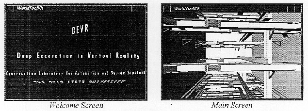
By using WTK functions, DEVR provides one welcome screen and one main screen in this program. The former screen shows 3D self-rotating text (string) objects, and the latter screen will load the whole models into the universe (Figure 2), that can be navigated using the mouse. When the program begins, the welcome screen displays as the first universe. Users can switch to the main program via the keyboard.
The Virtual Reality Modeling Language (VRML) is a programming language for describing multi-participant interactive simulations -- virtual worlds networked via the global internet and hvperlinked with the World Wide Web (WWW). Any virtual world display, interaction, or internet transmission can be specified by using VRML. It is projected that VRML will become the standard language of interactive simulation within the WWW.
VRML is to 3D what HTML (HyperText Markup Language) is to two-dimemsion (2D). While HTML specifies how 2D documents are represented, VRML is a format that describes how 3D environments can be explored and created on the WWW. Since 2D is really just a subspace of 3D, any 2D object can be easily represented in a 3D environment. VRML appears to be the future for the WWW because it is more natural to be immersed in a 3D space than to click one's way through hyperlinked pages.
The VR application in computer science, just like the WWW development on the internet, has become the most promising new technology in recent years. VR application provides a visualized VE. The WWW is the most efficient and powerful hypermedia to transmit the information to the public. VRML is the tool which combines both of them. The combination of VR and WWW can be further applied to many areas in Civil Engineering, such as education, practical training, communication, and construction.
3D File Format in VRML
In VRML, the 3D model has to be converted into the file format with the *.WRL file extension, which is entirely different with 3D Studio format (3DS), Drawing eXchange Format (DXF), Neutral File Format (NFF), or any other 3D file formats. The objects in DEVR are created in a 3DS file format in 3D Studio. In order to hyperlink VRML format files on the WWW, it is necessary to convert these 3DS files to a VRML file format, the 3D file extension for VRML.
VRML Browsers
Not only can a VRML browser provide a window for users to view the virtual models on the WWW, but it also enables virtual travel in this world from one's desktop. Users can experience a 3D photographic or rendered representation of any person, place or object. By using the mouse and keyboard, they can also rotate objects, zoom in or out of a scene, look around 360 degrees, and navigate from one scene to another.
There are numerous VRML browsers or viewers, the requirement to navigate the VE on the internet, from different computer development corporations. Shareware is available on the WWW such as Topper (Autodesk), Live3D (Netscape), Cosmo Player (SGI), QuickTimeVR Viewer (Apple). Each of these has different versions for different platforms.
WWW Version of DEVR
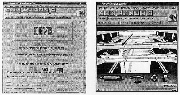
In order to reach a wide audience, this program has been successfully rewritten as a WWW Version1. Three changes were made (two transformations and the addition of text files) in converting the WTK version to the WWW version. The first transformation was to convert the 3DS files to WRL (VRML format) files. This can be achieved either by 3D converters or VRML. The second change was to convert the animation files rendered with extension FLC in 3D studio to compressed image file format for animation with extension GIF. A GIF file will be treated not only as an image file in WWW, but also as a combination of sets of image files, i.e. an animation file. The converters also are available on the internet. The last difference is that the WWW version should have the text files of the HTML format. The images of the DEVR homepage and the rendering result of 3D models are shown in Figure 3.
Conclusions
Given the current technology deep excavation may be the best way to resolve the problem of insufficient space during construction in a dense city. The DEVR program is a VR application for training and educational purposes in deep excavation.
Three stages are required to achieve the VR results in this program: 3D modeling, VE programming and VR presentation. The 3D graphical objects are created in 3D Studio in the first stage; the special attributes (such as universe, light, viewpoint, sensor) of the virtual environment are specified via the WTK library (using the C language) in the second stage; and the 3D models are imported into the VE in the final stage. As a further enhancement, the DEVR system has been placed on the WWW which is made possible by the Virtual Reality Modeling Language (VRML), that enables multiple users to interact with the 3D models simultaneously.
VR applications or VRML are relatively new technologies, and they both provide a VE to navigate in the 3D models. However, in their current state these two technologies do have limitations. These benefits and limitations are further discussed in the following subsections.
The Benefits of Virtual Reality
A common question regarding the DEVR program is, "Why use VR, since the appearance and animation of construction can be easily accomplished through videos, photographs and simple text descriptions?" To answer this question, let us consider the benefits of VR from three different points of view.
From a general point of view: The development of VR has successfully enabled a highly realistic 3D rendering performance, which can not be achieved by pictures or texts. While video definitely provides a more realistic animation display than VR, it appeals to us that the sense of visualization in VR is superior to any other type of media. In other words, VR offers users a more immersive application than others.
From an engineer's point of view: It is difficult to display some operations by using texts, pictures, or videos in a construction site. Taking the example of tunnel construction, entering a Tunnel Boring Machine (TBM) to take a photo or video of ring erection or jack extension for launching the TBM would be impractical. Another example is a deep excavation site. Engineers familiar with such sites know the difficulty of examining or photographing the wale connection in a specific layer and corner because the only space available for the workers there is the decking plates level, excavating level, and temporary stairs or elevators. 3D models and VR eliminate the need for videos and photographs and thus overcome these difficulties.
From a practical point of view: The construction sequences can be recorded by photos and videos; however, the viewpoints or viewpoint movement of these sequences are fixed. To record completed construction sequences with photos and videos is a time-consuming job, one that would require starting all over again when the users want to see the construction activities from different viewpoints. VR applications allow users to navigate the models from any viewpoint and to create any possible animation by simply recording the objects and viewpoillt movement. For this reason, the VR application is a better choice than other types of media.
Limitations
VR application in construction can be considered a great development for traditional civil engineering. This program focuses on deep excavation, a very general process which includes many important accompanying activities, such as the construction of slurry walls, pin piles. foundation piles, a decking system, a dewatering system, building protection, a monitoring system, and a traffic maintenance plan. Rendering every construction activity in detail is complicated and time-consuming, therefore, one important objective of this program is to provide the methodology for developing a deep excavation program by VR, which can be used as a pattern for further enhancements. We chose to concentrate on a single activity to develop a precise and defined system for more realistic rendering and near real time user interaction. Establishing such a methodological pattern is the main rationale for developing this program.
The preliminary stage of VR is the 3D modeling process. A real object can be defined by using a 3D model or 2D expressions (figures or text descriptions). The former may provide users with a more friendly and clear appearance than the latter; however, 3D models fail to easily give some basic factors for this object compared to 2D expressions. For example, illustrating every dimension of an object is cumbersome for a 3D model. It is also difficult to explain the weight or density of an object through use of a 3D model alone.
Another limitation of VR is that the texture mapping and shading process consumes a substantial amount of memory. Furthermore, texture mapping, which refers to the operation of applying a designated material or texture onto a polygon of one 3D object; shading, the rendering of a color gradient on a polygon due to light effects, both result in a poor frame rate if the 3D models contain many polygons.
Recommendations
Deep excavation can be considered as experience-oriented work so defining the construction events and sequences with regular rules can be problematic. Thus, developing a deep excavation program which could be adopted to any kind of situation would be very helpful to junior engineers and students. Based on the difficulties met so far, the authors would like to recommend using virtual doors, child programs and small models.
(1) Virtual Doors
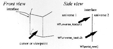
A virtual door is simply a 3D graphical object which is designed to be used as a door. The procedure is to determine a polygon of this object as the interface. When this interface is penetrated (touched) by the sensor or viewpoint, the universe will change from the original one to another when this door is penetrated by the viewpoint. A virtual door can be created by using either WTK portal functions or NFF portal properties. The virtual door concept and the corresponding functions are illustrate in Figure 4.
The virtual door idea can be combined with the child program concept. Users can select any button, which can retrieve and load the specific universe and objects. The function of a virtual door is similar to that of a menu bar or task icon which provides users with a friendly and efficient way to execute the program. The limitation of the virtual door in WTK is that all the 3D files should be converted to the neutral file format, because some WTK functions only work on NFF files. For example, WTuniverse_id2poly is a function which can only determine a specific polygon of an NFF object as the interface of the virtual door.
(2) Child Programs
The DEVR can be considered as a parent program which can incorporate dozens of child programs. A child program defines a specific event or one (or several) sub-event(s). One advantage of using child programs is that each of them can be restricted in a specific subevent and designed by specific designers. The program will become more professional and efficient if it is structured as one main program with several child programs.
Due to the variety of conditions in the construction site, each activity may have several options. For example, the bracing system can adopt inner bracing members (struts) or outer bracing members (ground anchors); or the building protection can be achieved by rail piles, secant piles, or an underpinning method. The multiple combinations of every activity are flexible and complex in a real situation. Another advantage of a child program is that each kind of event can be designed as an individual program in a specific VE, which can be linked to the main program via the keyboard or a virtual door. DEVR will become more integrated and adaptable for each condition with the aid of child programs. The concept of child programs is further illustrated in Figure 5.
(3) Simple Models
For better rendering results in a VR application, adopting simple models is suggested. A simple model is one that uses the least number of vertices and polygons to compose a model, and thus occupy less memory than usual. Although a simple model will reduce the level of reality" in an application, the rendering speed (frame rate) will be greatly improved. In the development of DEVR, the frame per second (FPS) becomes poor in the WTK when the size of a 3D model is larger than 0.6 megabytes.
According to the modeling and programming development of DEVR, the file size will at least double when a 3DS format file is converted into a NFF, DXF, or WRL forrnat file. WTK can accept 3DS, DXF, or NFF files, but some WTK functions, such as portal fiunctions, only work in the NFF files. Therefore, the 3D model designer need to be mindiill of the size of the 3D model when he or she creates the model in a 3DS format. The memory limitations of WTK are around 2 megabytes for the Windows version, and around 5 megabytes for the SGI Platform
Future Development by using VR and WWW
As mentioned above, this program has been successfully imported onto the WWW, the most promising and powerful media for the future. The combination of VR and WWW enables this program to be operated by several users at the same time. Moreover, if the WWW version is integrated with individual workstations, the DEVR program can be developed as a 3D communication tool between instructors and students, designers and engineers, or owners and contractors. Further information is available via http://class.eng.ohio-state.edu/ or http://class.eng.ohio-state.edu/jeng/devr.html
3D Studio. [1994]. 3D Studio Release 3 Manual. Autodesk, Inc., California.
AutoCAD. [1994]. AutoCAD Release 12 Manual. Autodesk, Inc., California.
Bell. Gavin. [1996]. "VRML Version 2.0 Specification." Silicon Graphics, Inc., California.
B+B/Eastern J. V. [1995], CC277 Bracing System Construction Method of Statement. Bilfinger+Berger Construction Co./Eastern Construction Co., Joint Venture, Taipei, Taiwan.
B+B/Eastern J. V. [1994], CC277 Decking System Construction Method of Statement. Bilfinger+Berger Construction Co./Eastern Construction Co., Joint Venture, Taipei, Taiwan.
Hadipriono, F.C., Barsoum, A.S., Tsay, T.C., and Nemeth, Z.A., [1994]. "Intelligent Traffic Evaluator for Prompt Incident Detection in Virtual Reality environment (INTREPID-VR),Intelligent Vehicle and Highway Systems (IVHS)-OSU, Report No. 94-07, The Ohio State University, Columbus, Ohio.
Hadipriono, F.C., Tsay, J., and Larew, R.E. [1996]. "Interactive and Immersive Training in Virtual Environment for Bridge Construction," a paper, The 1996 American Society of Engineering Education Annual Conference, Washington, D. C.
Hadipriono, F.C. [1996]. "Virtual Reality Application in Civil Engineering," ACM Symposium on Virtual Reality Software and Technology, Hong Kong.
Hadipriono, F.C. and Larew, R.E., [1996]. "Safety Training in Virtual Construction Environment," International Conference on Implementation of Safety and Health on Construction Sites, Lisbon, Portugal.
Pementel, K and Teixeira, K. [1993]. Virtual Reality: Through the new looking glass 1st Ed., McGraw-Hill, Inc.
WTK. [1993]. "World Tool Kit for Windows Version 2.02 Manual." Sense8 Inc.. California.
WTK. [1993]. "World Tool Kit for Onyx Platforrn Version 2.1 Hardware Guide." Sense8 Corporation., California.
WTK. [1993]. "World Tool Kit for Onyx Platforrn Version 2.1 Reference Manual." Sense8 Corporation., California.
1 Refer to the DEVR homepage in WWW by http://class.eng.ohio-state.edu/jeng/devr.html
 Back to Table of
Contents
Back to Table of
Contents