3-D HIGHWAY CONSTRUCTION PROGRESS SIMULATION USING VRML
ABSTRACT
Current management techniques provide primarily numerical data to construction professionals. However, the visualization of a construction project is essential to the inspection of its progress. While practical site experience is a means of visualizing construction progress, site visits can be dangerous and expensive. This paper presents a new methodology for simulating and distributing the progress of construction projects. Both continuous and discrete construction progress simulation are considered. Moreover, a three-dimensional (3-D) object database is established in a text format. The progress of a construction project can then be achieved easily and visually. Virtual Reality Modeling Language (VRML) is used to generate the 3-D simulation of construction projects, and the World Wide Web (WWW) is employed to distribute the 3-D models. Therefore, construction progress simulation information can be reached from any location in the world.
INTRODUCTION
The progress control of a construction project is essential to its success. Techniques have been developed for enhancing the management of construction progress. Critical Path Method (CPM), Bart Chart, and other network analyses have been implemented for progress planning and examination. In addition, research has been done to visualize the progress of construction. However, most software for visualization of construction projects is still limited to a two-dimensional (2-D) domain. Due to the rapid improvement of computer graphics in recent years, 3-D modeling tools have begun to play a significant role in the fields of design, architecture, bio-chemistry, and so forth. Construction companies also use these tools to view their designs and visualize the construction plans. By combining the scheduling information in the 3-D modeling tools, the management of construction is now stepping into a four-dimensional (4-D) era.
This paper implements the time warping concept of graphic animation into the 3-D modeling of construction projects to provide progress simulation. The WWW can be employed in future development to provide the access and transportation of the progress information. Based on its architecture, WWW provides a centralized and controlled environment for information distribution. It also provides great accessibility. Via the WWW, the 3-D simulation can be projected by using VRML, while numerical and text data are transported using Hyper Text Markup Language (HTML). Furthermore, the Common Gateway Interface (CGI) of the WWW gives remote users the capability to access provided information in an interactive manner.
Therefore, implementation of the study in this paper is expected to improve the communication among parties of a construction project by providing real time information and 3-D visualization via WWW. In addition, the result of this study can be a simulation tool for construction education by providing the students with vivid 3-D images of experimental construction projects.
3D VISUALIZATION
Due to a dramatic increase in the capability of a PC computer, 3-D visualization has been widely adopted in engineering research and applications [Hadipriono 1996]. Commercial 3-D Computer Added Design (CAD) and development packages are also available. Thus, various 3-D modeling descriptions are designed specifically for each package. Table 1 shows some common usage of 3-D file formats.
Table 1. Some 3D file formats [Rule 1996]
| Format | Application | Type of Format | Platform |
| 3DS | 3D Studio | Binary | PC |
| COB | TrueSpace | ASCII | PC |
| DXF | AutoCAD | ASCII | PC |
| NFF-WTK | World Toolkit | ASCII | PC/UNIX* |
| OBJ | Wavefront | ASCII | PC/UNIX |
| POV | POVRay | ASCII | Multi-platform |
| RAW | Open Standard | ASCII | Multi-platform |
| VRML | Open Standard | ASCII | Multi-platform |
*updated by the authors of this paper.
In order to achieve the best use of our program, a proper 3-D file format is essential. The ideal file format for this study is one that easily accessible and maintainable. With its advantages, VRML met these requirements and was selected to be used in this study. The advantages of VRML are: independence, WWW applicability, and easy manipulation and maintenance. First, most of the file formats in Table 1 are designed for a specific application. Therefore, they are dependent on the application. Using these file formats, a 3-D demonstration is not achievable without its application. On the other hand, VRML is designed as an open standard for the International Standard Organization (ISO). Besides, VRML is a multi-platform script. It can be used on all different types of computers. A great number of companies have developed the viewer for VRML. Second, VRML models can be seen directly via the Internet connection. Models generated by using VRML can be reached from all over the world via the WWW. Third, VRML is in plain text format (ASCII format). Hence, a VRML model script is readable and understandable. It can be manipulated as pure text in programming or database. Based on these advantages, VRML is one of the most popular 3-D file formats, and it is suitable for simulating the construction progress in this study.
CONSTRUCTION PROGRESS SIMULATION
The progress control is vital for a construction project's success. Due to the increased complexity of construction planning techniques, the tracking of a construction project has become more difficult than before. An easy-to-understand presentation of the project progress is needed. Thus, a visualized construction progress representation is developed in the paper for efficient and effective progress control. In the planning stage, the visual simulation of construction can provide a clear illustration of the construction method and sequence. Design professions can identify problems and solve them during the planning stage. After the construction has started, progress control is important for the contractor in order to avoid project delay and eliminate disputes due to the delays. Project managers can perceive progress information visually instead of numerically.
To simulate the progress of a construction project, a detailed construction plan is required. Three kinds of information are needed for performing a visual simulation: the physical construction components, the construction schedule, and the construction method. The physical construction components include all the visible products of the project, for example, the pavement and infrastructure designs of a highway construction project, visible components in the construction process are incorporated. The site survey or soil tests, which have no visible on-site products, are not incorporated. The project schedule indicates the sequence and time frame of project activities. The production of the project is assumed to be proportional to the time consumed. The construction method describes the way construction progresses. Generally, the construction methods are determined based on the factors of equipment availability, time, site condition, design, and workers. Construction method information used in this study is simplified. It is used only to indicate the direction of progress (horizontal or vertical) of each activity or component.
Construction progress can be presented by two variables: elapsed time and completed material quantities. These two factors are used in different stages of the construction process. In the planning stage, the completion of an activity can only be simulated based on the assigned time schedule. Assuming that the production rate is uniform throughout the whole activity, construction components are to be constructed in proportion to the elapsed schedule time. The influence of a learning curve and mobilization are not incorporated in this study. In the construction stage, the progress simulation is more accurate by using the actual completed material quantity as the control factor, then following the predetermined construction schedule. The simulated construction components are to be illustrated proportionally to the completed material quantity. For example, a concrete drainage trench is scheduled to be constructed in a duration from Time 1 to Time 2. Thus, the trench is to be presented as zero length at Time 1 and as full design length at Time 2. On the other hand, if the quantity of concrete needed for the trench is 100 cubic-yards (76.46 cubic-meters) and 50 cubic-yards (38.23 cubic-meters) of concrete has been consumed, the trench should then be half completed.
To simulate the continuous construction progress, the completed portion of a project component can be calculated using the following equations. The first equation represents the time factor, and the second one represents the quantity factor:
d = D × ( t - ts ) / ( tf - ts ) (1)
or
d = D × qc / qt. (2)
Here,
d: currently completed portion in simulation,
D: original object design,
t: current time,
ts: activity start time,
tf: activity finish time,
qc: consumed material quantity,
qt: total quantity of material needed.
Currently, many researchers have implemented 3-D CAD object in process simulations [Tavakoli et al. 1991, Collier and Fischer 1995, Fischer and Aalami 1996]. 3-D models are generated separately in CAD programs prior to the integrated visual demonstration. Thus, the dimensions of models are predetermined and cannot be changed during a simulation. Two options are given to users: i.e., whether to show the complete model in the virtual world or not. When only these two options are given, difficulties can be found in simulating continuous progress. Thus, a discrete progress representation is used. To perform the simulation, construction objects are sub-divided into pieces. As the project progresses, each piece is then added into the 3-D demonstration. Thus, a fine sub-division of the original design component provides better simulations of its continuous progress. In this study, object models are generated dynamically using VRML descriptions. According to its expected progress, dimensions of each objects are calculated using Equations 1 and 2. Therefore, progress simulation can be performed precisely.
Nonetheless, some integrated components do not progress continuously. Integrated components include pre-cast or pre-fabricate components. They are assembled or placed on site unit by unit. These might include pre-cast barriers, traffic signs and lighting devices. For integrated components, the discrete approach is needed. The number of units shown in the simulation can be calculated using Equation 3.
n = [N × ( t - ts ) / ( tf - ts ) ] (3)
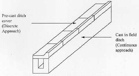
In the equation, n is the number of units completed in the progress simulation, and N is the total number of units scheduled in the activity. The 'floor' operator ( ) returns the integer of a fraction number. Based on these equations, the progress of a construction project can then be simulated accurately and vividly. These two approaches are used alternatively for the simulation. Figure 1 shows an example of these two approaches and Figure 2 shows the simulation result in VRML.
Figure 1. Different components of a ditch model up
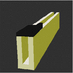
Figure 2. VRML implementation of a ditch model up
IMPLEMENTATION
Uniqueness and inconsistency are two special characteristics of construction projects. The component designs of construction projects are different from project to project. Thus, a flexible system is needed. The software resulting from this study must have the capability of being implemented for different construction projects. The capability to constantly update and edit the data used in the system is needed. Therefore, data objects are used for the implementation of this study.
To perform the simulation, two database files are established: object and material database. The object database stores the VRML descriptions of objects and variables. Objects are elementary 3-D components used in the 3-D world, such as a cube, block, cylinder, sphere, and cone. The variable indicates the dimensions of the object. An object can be a combination of other objects. For example, the street lamp shown in Figure 3 is a combination of two cylinders and a cone. Figure 4 shows the object editing screen. A material database consists of the description of each construction material and its visual properties, such as color and texture. Based on these two databases, the design of a construction project is described as a combination of different components. For example, a concrete pavement layer can be expressed as a concrete (material) block (object) and its dimensions (object variable).
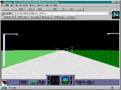
Figure 3. Street lamp model [Lee et al. 1997] up
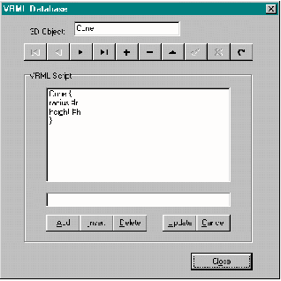
Figure 4. Object manipulation screen up
The 3-D simulation generating process is shown in Figure 5. First, the generator gathers all the information needed for the simulation; including the design, schedule, and quantity data. Second, it computes the expected dimensions of all the objects in the projects. Third, it retrieves the VRML description and material properties from databases and creates VRML scripts accordingly. Finally, it applies the proper translation and rotation to the object and outputs the final VRML scripts to a file (or directly to network). The 3-D demonstration is then available on a VRML viewer.
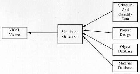
Figure 5. A 3-D simulation generating process up
CONCLUSION
Due to the increase of computer capabilities, the long needed implementation of a 3-D visualization for construction projects is now feasible. The difficulties that we had to overcome were the inconsistency of construction projects and the maintenance of system flexibility. Focusing on the solution of these two difficulties, this paper implements a texture description database for 3-D object modeling. The 3-D objects are generated and stored in the database. It also provides a flexible environment that allows users to easily modify and update 3-D objects. In addition, VRML is used for the 3-D modeling in this paper so that the user can view the 3-D progress demonstration through the WWW. By combining this study with CGI application, interactive and dynamic communication of construction can be achieved through the WWW in real time [Lee et al. 1997]. The range of construction management can now be extended world wide.
REFERENCES
Collier, Eric, and Fischer, Martin (1995). "Four-Dimensional Modeling in Design and Construction." Technical Report, Nr.101, CIFE, Stanford.
Fischer, Martin A. and Aalami, Florian (1996) "Scheduling with Computer-Interpretable Construction Method Models." Journal of Construction Engineering and Management. Dec 1996. p 337-347.
Hadipriono, F.C. (1996) "Virtual Reality Applications in Civil Engineering," ACM Symposium on Virtual Reality Software and Technology 1996, Hong Kong. pp. 93-100, 196-197.
Lee, Jen-Rong; Hadipriono, Fabian C. and Larew, Richard E. (1997) "Implementing VRML and Object-Oriented Techniques in a Pavement Construction Management System." Proceedings of the International Conference on Simulation and Multimedia in Engineering Education (ICSEE'97). SCS Publishing, San Diego, Simulation Series, Vol.29, No.2. pp165-170.
Rule, Keith. (1996). 3D Graphics File Formats. Addison-Wesley Publishing Company, Inc. September.
Tavakoli, Amir; Klika, Kenneth L . (1991) "Construction management with AutoCAD." Journal of Management in Engineering. v 7 n 3 Jul 1991 p 267-278.
 Back to Table of
Contents
Back to Table of
Contents