AUTOMATIC THREE-PHASE SQUIRREL-CAGE INDUCTION MOTOR TEST ASSEMBLY FOR MOTOR THERMAL BEHAVIOR STUDIES
ABSTRACT
This paper presents an experiment to show to the students the importance of the temperature on the performance of the three-phase squirrel cage induction motor. Is is presented a laboratory assembly to perform, automatically, three-phase squirrel-cage induction motor load tests. Besides the motor, mechanical load (fan), drive and electrical protection equipment, the assembly comprises a 12 bits data acquisition system, a software controlled electronic driving system, temperature sensors and a microcomputer. It is useful for fast and reliable motor part temperatures acquisition during any proposed load test, via computer keyboard, allowing for the data storage for motor thermal behavior studies. The performance of the assembly was checked by performing load tests according to the duty types proposed in [1].
INTRODUCTION
The IEC 34-1 [1] defines a duty as "the statement of the load(s) to which the machine is subjected, including, if applicable, starting, electric braking, no-load and rest and de-energized periods, and including the durations and sequence in time". Rest and de-energized is defined as "the complete absence of all movement and of all electrical supply or mechanical drive".
IEC 34-1 defines also the duty type as being continuous, short-time, periodic duty and non-periodic duty. Periodic duty includes constant load(s) with specified duration that constitute a duty cycle itself along the time and non-periodic duty includes load and speed variations in the operating range. It is also defined thermal equilibrium as "The state reached when the temperature rises of the several parts of the machine do not vary by more than 2K over a period of 1 hour" and cyclic duration factor as "the ratio between the period of loading, including starting and electric braking, and the duration of the duty cycle, expressed as a percentage".
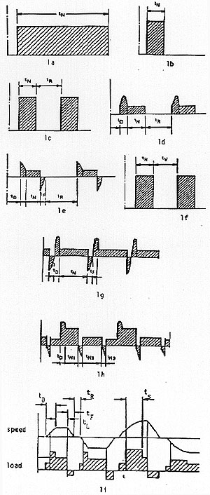
The duty types defined by [1] are:
9. Duty with non-periodic load and speed variation - duty type S9 - "A duty in which generally load and speed are varying non-periodically within the permissible operating range. This duty includes frequently applied overloads that may greatly exceed the full loads" (Figure 1i). In this duty type, tL = operation under various loads time, tS = operation under overload time.
Figure 1. Duty types - IEC-34-1 1 - load x time. up
The load duty for some drive may be described by one of the duty types among the nine types presented in [1] or by another duty specification by the motor purchaser. It is a purchaser responsability to specify the duty as well as possible to the manufacturer to manufacture the right motor.
If the duty is not specified by the purchaser, duty type S1 is imposed and the class of rating assigned shall be maximum continuous rating.
If machine shall be applied to a S2 to S9 duties the rating shall be based on the correspondent duty.
In [1] it is mentioned that machine load test, in manufacturer plant, can be done using the equivalent continuous rating for machines complying with S3 to S9 duties. The standard [1] does not specify how to calculate the equivalent continuous rating but the rms power value is frequently used according to the agreement between manufacturer and purchaser.
The equivalent rms power value can be calculated for any duty like that presented in Figure 2 as an example. For Figure 2a, the rms is given by (1)
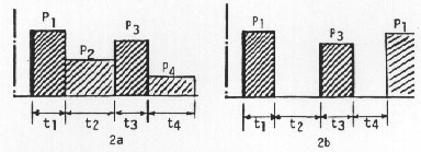
Figure 2. Equivalent power example - load x time. up
 (1)
(1)
For Figure 2b the rms is given by (2)
 (2)
(2)
When it is necessary to specify a motor for a specific drive, there are two possibilities: a) to follow the IEC or equivalent standards recommendations specifying a special machine to the manufacturer. This procedure is currently used to specify large motors (larger than 200 HP) that are not series manufactured but it is generally avoided to specify small motors (less than 200 HP) because it results in special motors and so very expensive when compared with series manufactured motors (catalog motors), b) to specify a catalog motor is what people use to do when possible.
Papers [2] and [3] present a simulation method that can be used to help the designer for the duty definition, catalog motor selection and, if necessary, for the equivalent power calculation. To do the researches reported in [2] it was necessary to develop the automatic test assembly reported in this paper. This test assembly can be used also by motor manufacturers in their test area, by O&M having a large number of motors, in workshops, in electrical machine technology research centers and also in educational electrical machine laboratories.
AUTOMATIC TEST ASSEMBLY DESCRIPTION
For thermal behavior tests of three-phase squirrel-cage induction motors, fed directly from the grid or from power electronic converters, it is necessary: a) to install temperature sensors in several parts of the machine, b) to run the machine according to the duty type specified by IEC [1], as mentioned before, or by the user, c) to record instantaneous temperature values during machine run.
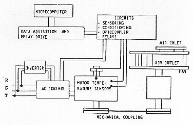
The automatic test assembly is an experimental electrical machine assembly (Figure 3) developed to accomplish with the described subject mentioned above. It is composed by the motor and the mechanical load (fan), switches, contactors, electrical protection devices, inverter, data acquisition card with sensing circuits, temperature sensors for motor and ambient air, contactor relays control circuits and a microcomputer.
Figure 3. Experimental electrical machine assembly. up
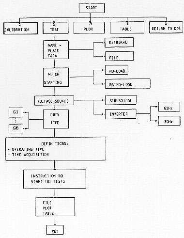
System is automatized and controlled by the microcomputer allowing, through a specific
software, for selection of: a) power source type (grid or converter), b) starting type (no-load or
rated-load), c) type of duty, d) duration of each part of the operation cycle for the different
duties (time-on, time-off including starting, stopping and braking), e) number of temperature
values to be acquired and storaged. Its output allows for data table and plot construction.
The automatic test assembly allows for a sequence of any number of tests since it is
programmed in the computer.
The selection of power source and the operation time interval (time-on, time-off, starting,
stopping and electrical braking) are done by the microcomputer that send pulses to operate the
contactors and relays through the relays control circuits. Each relay is operated according to the
developed software.
The temperatures, acquired by temperature sensors, in the stator winding, in the stator and
rotor
cores and in the ambient air are conditioned, filtered, converted into digital in a 12 bits A/D
converter and stored in files in the computer HD. When test or tests finish motor is stopped
automatically and data can be edited in tables, plots or treated numerically in a proper software.
Computer program allows for real time system operation and details of temperature sensors,
sensor circuits, conditioning circuits, data acquisition card, relays control circuits and software
are provided as follows.
TEMPERATURE SENSORS AND SIGNAL
CONDITIONING
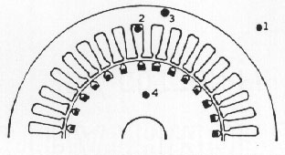
Figure 4 shows a motor section with the four
temperature sensor positions. The sensors used are
the very small metal encapsulated integrated circuit Intersil type AD 590JH.
Figure 4. Motor sensor positions. up
This device provides a linear output current related to the temperature. The ratio
current/temperature is 1µA/°K between 218°K and 429°K and it is
possible to calibrate it.
The device is insensible to voltage drops on the conductors due to its very high impedance to
the
output current, so that it can be installed far from the reading circuit.
To put the sensor in the stator and rotor cores, holes were drilled in the machine stator and
rotor
lamination packs without disassembly them. To put the sensor in the stator winding it was
necessary to dismount it partially to erase the coils.
As the tests were conducted in a 3 HP motor it was not possible to insert a sensor in the rotor
bar.
This would be possible in larger machines. To get the rotor core temperature, a couple of slip
rings and brushes were used without problem because the sensor is free from voltage drop
on the brushes across the measurement circuit.
To use the voltage signal, got from the temperature sensor, it is necessary to condition it
properly
to the AD converter voltage range.
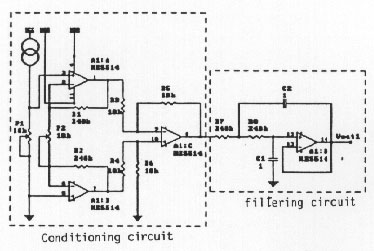
The AD converter used is the Analog Devices AD674. The circuit of
Figure 5 permits to deal
with analog input in the range of 0 V to +10 V (pin 13) and 0 V to +20 V (pin 14) and uses 3
operational amplifiers, that are instrumentation amplifiers in the non-inverter configuration, as a
signal conditioning circuit.
Figure 5. Sensing circuit. up
The gain is got just adjusting the potenciometer P2 and, next to the signal
conditioning, there is
a signal filter.
The filter is an active lowpass 2nd order (Butterworth) that presents a good
response from 0 Hz
to the determined cutoff frequency (fc) where the gain of the storage felt to 0,707, in other
words, -3 dB. In the case of Figure 5, where R1 = R2 = 240 k, R3 = R4 = R5 = R6 = 10 k,
R7 = R8 = 240 k, all of them 1 % tolerance, C1 = C2 = 47 nF it has fc = 14 Hz. The filter is
necessary to eliminate the high frequency signals, electrical and electromagnetic interference
noises.
The complete sensing circuit uses the integrated circuit NE5514 from Phillips that has 4
encapsulated op-amp. Filter output is directly connected to one of the multiplexer input channels
in the data acquisition card.
DATA ACQUISITION CARD
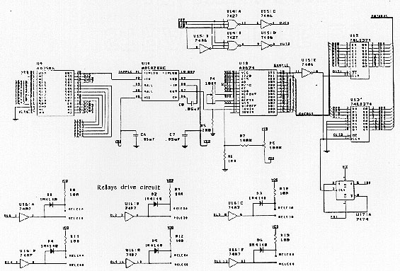
The data acquisition card could be bought from any manufacturer but it was designed and
constructed by the authors. Figure 6 shows the data
acquisition card drawing that comprises the
multiplexing, sample & holding and the A/D conversion stages. The output of each sensing
circuit (in this case there are 4) are connected to one of the multplexer inputs; the multiplexer
selects, in a sequential way, among their input channels, the one which is the desired at each time
and connects it to its output during a specific time interval.
During this time interval a sample & hold circuit freeses the instantaneous value of this
signal
while the A/C converter converts it to the digital form. This digital instantaneous value is sent to
the microcomputer or to a microprocessor (in this case it was used a PC AT 486
microcomputer).
The multiplexer used is the AD 7506, the sample & hold is the AD 583 HC, and the A/D
converter is the AD674AJ, all of them from Analog Devices. A reading enabling circuit using
two AND gates (7427) and three inverters (7486) is necessary to permit that any input channel
could be selected and be able at the multiplexer output.
Figure 6. Data acquisition card drawing with relay drives. up
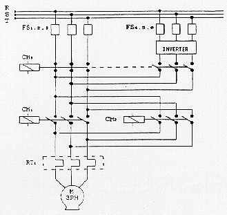
RELAYS CONTROL CIRCUIT
To make the system automatized it is necessary to have a relays control circuit. The AC
motor
control is shown in Figure 7. The contactor CM1 is
used for motor starting and stopping. CM2 is
used in tests with electrical braking that is done by phase inversion with CM2; CM3 is used to
select the power source between the grid or the inverter.
Figure 7. AC motor control. up
To operate the contactors in order to automatize the system the five relays control circuits are
used, each one with a specific task (Figure 8).
The contactors control logic is shown in Table 1, where the logic level 0 is used to operate
the
desired relay.
Table. Contactors control logic.
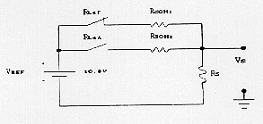
The relay RL4 is used to select the frequency of operation of the inverter when it is
to be
used. It can be selected 2 different frequencies 60 Hz and 30 Hz as shown in Figure 8.
If the relay RL4 is not operated the voltage frequency remains 60 Hz. The reference
voltage source (VREF) is
internal to the inverter and the voltage VS on the resistor RS is
proportional to the chosen frequency.
The fifth relay RL5 is used to control the motor load though the control of the air opening of
the fan using a solenoid.
Figure 8. Relay positions for motor operation. up
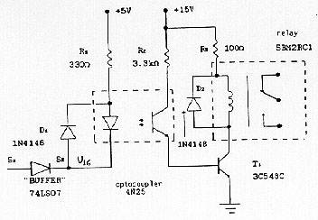
The relays control circuit schematic is shown in Figure
9. The drive block is constituted by the
register 74LS373 of 8 bits with parallel input and output (unit U1) and by buffer 74LS07 with
six drivers, unit U16.
Figure 9. Relay positions for frequency selection. up
The register is a relay selection unit. Through a control byte stored in unit U1 the desired
relay
is
selected. This process consists in the input a low level "0" in the driver unit U16 (Figure10).
Figure 10. Relay control circuit. up
The optocouplers are used because it is required an electrical insulation between the drive unit
and the relay.
The relay operation generates electromagnetic interference noise able to cause the
misoperation
of any contactor.
DATA ACQUISTION AND RELAYS CONTROL
SOFTWARE
The hardware shown before is supervised by the microcomputer that, through a software, a
permits its operation. The software establishes a communication between the user and the
microcomputer.
The programming language used is the Pascal 6.0 and the software permits: a) the testing
motor
temperatures acquisition according to the number of points given as input, b) to handle the
temperature data in tables or plots, c) to automatize the system allowing that all the motor type
duties prescribed by [1] could be performed via computer keyboard, d) the test performing in
real time with accurate and reliable results. e) to treat mathematically the output signals. The
block diagram is presented in the Figure 11.
Figure 11. Software block diagram. up
RESULTS
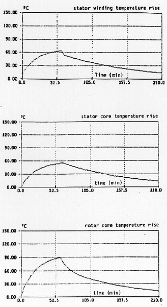
Figure 12 shows the stator winding, stator
core
and rotor core temperature rise x time curves for
duty type S2 with tN = 20 secs.
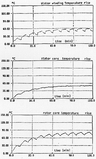
Figure 13 shows the same temperature rise for
duty type S4 with tN = 20 secs,
tD = 5 secs and tR = 5 secs.
Figure 12. S2 duty type (experimental). up
Figure 13. S4 duty type (experimental). up
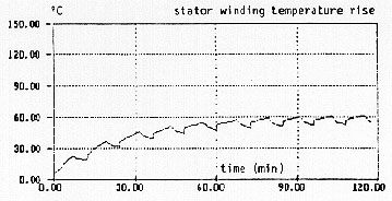
Figure 14. S4 duty type (simulation). down
Figure 14 shows the stator winding
temperature
rise x time curve for duty type S, with the
same times as in Figure 13, obtained by simulation using the dynamic mathematical model
presented in [2] and [3].
Results presented in [2] were checked also against test results measured using analog
ampermeter and all of them were quite equal showing that results got from this assembly are the
best at the best price.
CONCLUSIONS
This laboratory assembly can shows to electrical machine students the importance of the
temperature considerations in electrical machine loading.
Figures 12 to 14 shows that for any type of the load duty the temperature in each part of the
machine reaches its steady-state value. This steady-state value can not be higher than that
specified for each part of the machine.
In case of class B machines the stator winding temperature can not be higher than 120 K. So,
for
a maximum ambient temperature of 40 K. The stator winding temperature rise can not be higher
than 80 K. In the case of figure 13 it did not reach 60 K showing that it is possible to use the
same machine operating with a higher load in the same duty.
Figure 12 also shows the temperature behavior during starting and stopping. It is possible to
do
blocked-rotor test, successive starting tests and speed reversion tests that are tests that force the
machine termically.
ACKNOWLEDGEMENTS
The authors would like to thank FAPESP and CNPq for financial support of this research.
REFERENCES
Power Sourcer
Grid
Inverter
CM1
CM2
CM3
CM1
CM2
CM3
Starting
0
x
1
0
x
0
Rest
1
1
1
1
1
0
Breaking
0
1
1
1
0
0 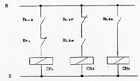
 Back to Table of
Contents
Back to Table of
Contents