DEVELOPING INTERDISCIPLINARY UNDERGRADUATE
AND
GRADUATE
COURSES THROUGH THE INTEGRATION OF RECENT RESEARCH RESULTS
INTO THE CURRICULA
Craig Friedrich, Associate Professor
Department of Mechanical Engineering and Engineering Mechanics
Robert O. Warrington, Dean
College of Engineering
Michigan Technological University
Houghton, MI 49931
phone:906-487-1922/fax:906-487-2822/email:craig@mtu.edu
ABSTRACT
This paper describes a three-year project at Louisiana Tech University to integrate a
multifaceted research program into the undergraduate and graduate engineering curricula. The
area
of
focus is precision micromanufacturing processes. Traditionally, precision engineering has
addressed
the fabrication and metrology of large components to high tolerances. The same
techniques and equipment, except for much of the tooling, have been applied to the fabrication of
micro-scale components with similar absolute tolerances. The results were integrated into the
curricula by way of a number of new graduate/undergraduate courses. The long-term goal is to
develop a graduate degree program in this vital technology.
INTRODUCTION
The precision micromanufacturing processes are those processes which do not utilize
lithography and chemical etching to remove material. The reason precision is used to describe
the processes is because many of the practices used in more conventional machining are also
used to help control errors at the micro scale. This results in the accuracy of micromechanical
processes being akin to those at the macro scale, generally in the sub-micrometer range.
To set the stage for the curricular development, each of the processes will be very briefly
introduced. Because these processes use mechanical, rather than chemical, means to remove
material they are also referred to as the micromechanical machining processes. The
micromechanical processes are comprised of the forceless (energy) and force (chip making)
processes.
FORCELESS PROCESSES
The forceless processes utilize energy for the direct removal of material. Among these
processes
are focused ion beam, laser, and electrical discharge micromachining.
Focused Ion Beam Micromachining
 Focused ion
beam micromachining (FIB) has been widely used in the semiconductor industry to
create very fine cross sections in electrical structures and junctions. The process uses an
accelerated beam of metal ions which impact the surface of the work material. The kinetic
energy of the ions results in atoms of the
work piece being dislodged from the surface
thus providing atomic-scale machining.
FIB is particularly useful for the fabrication
of micromechanical cutting tools.
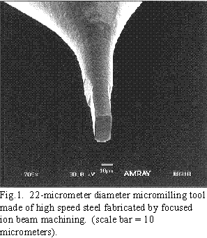
The tool shown in Fig. 1 was made by FIB.
A cylindrical tool blank is placed in the FIB
chamber with the tool axis perpendicular to
the incoming ion beam. The beam is
rastered within a rectangular area where
material is to be removed. Although the
milling tool may look symmetrical and able
to be used with either sense of rotation, only two of the edges
can be used for cutting [1].
Laser Microfabrication
 Materials
such
as ceramics and diamond have use in high temperature or corrosive
applications and these materials must sometimes be given complex geometries. Laser
micromachining typically uses a pulsed excimer laser with a wavelength of 248nm (KrF). The
pulse width lasts tens-of-nanoseconds and the pulse rate is normally 2 kHz or less. This gives a
relatively low duty cycle which, coupled with the
short pulse width, results in little thermal damage to
the material away from the ablated region.
The lasers used in this type of micromachining have
a non-symmetrical energy distribution. For this
reason, it is important to shape, or chop, the beam
so only the central portion is allowed to pass to the
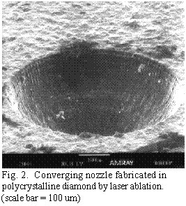
final focusing optics. This helps produce a more
predictable ablated profile as shown in Fig. 2 [2].
This micromachining technique does not have the
fine feature resolution or high tolerance as do the
processes with a distinct cutting interface. The
practical feature resolution is about a micrometer
and the repeatability of the process tolerances are
also in that range.
Laser Polymerization
 Certain
polymer photoresists can be polymerized by ultraviolet radiation. This process is similar
to conventional stereo-lithography except the spot is normally smaller and the thickness of the
layer of polymer to be polymerized is thinner. In the microscale process, the laser wavelength is
typically 351 nm from a XeF excimer laser. The power of the laser must be greatly reduced so
that ablation of the resist does not take place. This process requires additional capabilities and
hardware so that after a layer of the resist is "written" by the laser with the desired pattern, the
partially solidified material is immersed in the liquid polymer and raised so the surface of the
previously written layer is just micrometers below the surface of the liquid.
The work piece can be moved under the stationary beam or the beam may be steered by
auxiliary mirrors and actuators. If there is
sufficient laser power, the beam may be
expanded and a mask used which is more
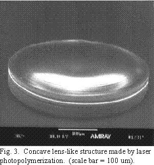
like conventional lithography. An example
of a structure made by laser
photopolymerization is shown in Fig. 3 [3].
Micro Electrical Discharge Machining
Again, as the name implies, this process is
the microscale version of the conventional
EDM process. In EDM, the amount of
material removed per spark is a function of
the energy which crosses the discharge gap.
Higher energy results in a higher removal
rate but a rougher surface because of the
crater left behind in the work piece. In
microEDM, the key is to limit the energy in
the discharge and this is typically done by
reducing the capacitance in the discharge
circuitry.
For electrodes with a diameter in the range of hundreds-of-micrometers, the energy of the
spark
is not as important in defining the overall geometry of the part feature. Of course as finer
finishes are required, even for larger parts, the spark energy is reduced and the frequency
increased. However, since in many micro-applications the feature size may be on the same size
scale as the surface finish variations in macroscale EDM, the stray capacitance in the EDM
machine may be the largest remaining source.
FORCE PROCESSES
The force processes are micromilling, microdrilling, and diamond micromachining.
Micromilling and drilling are normally performed on a high precision milling machine and
diamond machining is normally performed on a high precision lathe.
Micromilling
 The machining
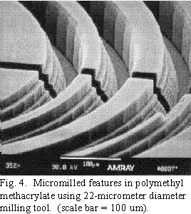
parameters for micromilling are dependent on the material being machined. For
the structure shown in Fig. 4., the spindle speed was 19000 rpm, the feed rate
was
35 um/sec
(feed of 55 nm per cutting edge), and the axial depth per pass was 4 um. The entire pattern had
a total of 35 million cubic micrometers removed and was accomplished in about 3 hours.
Although this may seem slow, it is actually a very rapid removal process for the microscale.
With these conditions, the tools did not break from static or fatigue loads.
 Micromilling
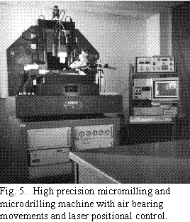
must be performed on a high precision machine tool with very smooth motions. In
such a tool, all motions should be on air bearings
with closed-loop positional control. This results in
very smooth movements, particularly at slow
speed where slip-stiction could result in tool
breakage due to a higher level of impact loading
on the cutting edges. High resolution feedback
also allows for continuous work table velocity at
slow speeds. An example of such a machine tool
is shown in Fig. 5. The milling machine is
largely composed of granite to provide vibrational
and thermal stability coupled with a large mass to
provide a low natural frequency [4-6].
Microdrilling
Microdrilling is always performed with a vee-block arrangement. This is because the drill can
not tolerate eccentricity of rotation which would
place very large bending loads on it, in addition to
axial columnar loads. Microdrills, smaller than
50 micrometers in diameter, are of the spade type.
The length-to-diameter ratio depends on the drill
diameter with an L/D of 4 to 7 being normal in
the 25 to 100 um range, and an L/D of more than
11 in larger drills made of tungsten carbide.
When microdrilling, a thin fluid is always recommended to help remove chips from the hole,
in
addition to the pecking action of the drill. This fluid can be air or an air-oil mist. A moving
fluid is preferred over a stagnant fluid drop because chips can flow back into the hole unless
effectively removed from the drilling site. The air-oil mist provides an additional level of friction
reduction and is therefore preferred over air alone.
Microdrilled holes can be made to high precision if
the drills are inspected and sized prior to use.
Typically, the tolerance on precision microdrills is
2.5 micrometers which may be excessive in critical
applications. Testing was performed to determine
the quality of microdrilled holes in terms of
diameter, straightness, and wall smoothness in a
semi-production situation. Drills were inspected
prior to use, except for a rapid break-in process
which consisted of drilling a few holes to small
depth. This was done to remove any residual burrs
left on the drill due to the grinding process. The
straightness of the holes was measured by inserting
a glass optical fiber and allowing the fibers to
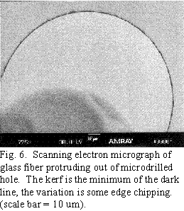
extend some distance beyond the part surface. By measuring the misalignment of the two fibers,
an indication of hole straightness, coupled with hole oversize, was found. The results were that
the two holes were repeatedly drilled in a number of parts with a non-parallelism of 0.08 degrees
(1.5 milli-radians) and the oversize of the hole was estimated to be 0.5 micrometers, as shown
in
Fig. 6. The holes had an L/D of 8.
Diamond Micromachining
Diamond machining is commonly used to produce
very smooth surfaces with highly precise geometry
for optical, and many other, applications. A variety
of microstructures can be made by diamond
machining because the tool geometry can have small
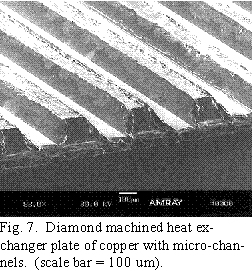
features. One such example is micro thermal surfaces
and applications. By machining parallel channels
into high conductivity copper, micro compact heat
exchangers can be realized with very high volumetric
heat transfer coefficients, as shown in Fig. 7 [7]. Each plate contains as many
channels as are feasible based on the overall size of
the device. The plates are then stacked such that the channel axes are perpendicular on adjacent
layers. The bottom of the upper plate forms the top of the channels in the lower plate. The
plates can then be joined by a process such as vacuum diffusion bonding which will provide a
good channel-to-channel fluid seal.
COURSE DEVELOPMENT
In support of the research efforts, and to provide an educational outlet for the research
results,
courses were developed in, and in support of, the micromechanical and microlithographic
processes. These courses were offered for graduate students and senior undergraduate students.
Because the technologies are very interdisciplinary, the courses drew students from most areas
within engineering and from the sciences. The courses were also developed with an
interdisciplinary approach. Each course had a laboratory component where students were
exposed to equipment by demonstrations without extensive theory (operation of a scanning
electron microscope, for example), or with direct hands-on use of the equipment (operation of a
high precision micromilling machine, for example). The courses were often team-taught by
faculty with varied backgrounds and sometimes the courses were co-developed with and
co-taught
with the students. This was particularly useful for interdisciplinary subjects, such as
photonics, where students from various disciplines took topics in their own area.
PROCESS COURSES
Theses courses formed the core of the micromanufacturing sequence. These courses exposed
students to the actual processes and equipment which could be applied to their particular projects
or theses. The courses were intended to be a summary of the processes since the student
enrollment was very interdisciplinary. After completing the course(s), a student was then able to
take a more in-depth approach and apply those concepts applicable to their particular problem.
Lithographic Processes
This course was developed first because it requires the least investment in equipment to be
meaningful. The basic process steps of optical lithography can be learned using conventional
approaches. With these approaches, working electrostatic motors were made with features sizes
in the 100 micrometer range. Additionally, patterned silicon etching can performed which
introduces such topics as etch rates, effects of etch temperature, etch planes, resist spinning,
mask preparation, and general clean room practices and materials safety practices. With more
advanced equipment, the processing scales can be reduced and smaller structures can be
realized.
Mask preparation can be accomplished with a high resolution printer (600 dpi for example)
and
normal overhead transparency material. Again, these techniques are generally limited to 100
micrometer, or so, lines and spaces. A resist spinner can be fabricated from nearly any variable
speed motor and contact printing can be performed.
Resist development and silicon 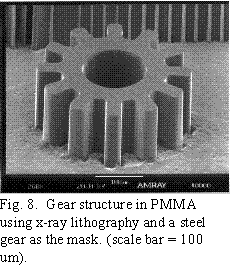 etching can
take place at the beaker-scale with a hot plate. This
course has evolved over 4 years and as new equipment
is acquired, it continues to evolve.
The IfM operates two beamlines on the CAMD
synchrotron near LSU-Baton Rouge. This afforded
students the opportunity to be exposed to deep x-ray
lithography. While conventional x-ray masks can be
complex components, nearly any small metallic
structure can serve as a mask. An example of this is
shown in Fig. 8. which is an exposure in PMMA
simply using a small metal gear as the mask. Such
mask structures can also be used with optical
lithography.
Examples of research results brought into the classroom include alternate x-ray mask
substrates
(graphite for example), electroforming of lithographic molds for structure fabrication, electron
beam lithography using a scanning electron microscope, and laser-produced lithographic masks.
Micromechanical Machining Processes
The micromechanical processes already described form the basis of this course. Because
these
processes require good dimensional control to be effective, this course also introduced the basics
of precision practices including effects and methods for controlling errors from thermal and
vibration effects, lack of straightness and flatness in machine slides, and feedback and tooling
errors, for example. Each process was addressed separately with a laboratory exercise and
students chose one or more processes with which to conduct a term-long project. These projects
ranged from direct machining of optical lithography masks, to biomedical transducer prototypes,
to passages for microchemical reactors and most often formed the basic work for graduate
theses.
In the laboratory exercises, thorough experimental practices were emphasized. This is
because
of the research oriented nature of the course. Because micromechanical machining is not widely
practiced, experimental data was often incorporated into technical publications on the process(s).
Such an example is microscale metal cutting. Conventional cutting mechanics are based on a
perfectly sharp cutting edge or a cutting edge with a radius which is small compared to the uncut
chip thickness. In microdrilling, for example, the cutting edge radius is typically 1 to 1.5
micrometers while the uncut chip thickness (feed) is typically in the 10 to 100 nanometer range.
On the conventional scale, this is the same as machining with an extremely worn cutting tool.
The conventional mechanics approach must be altered to account for the fact that the effective
rake angle of cutting is typically -85 to -88 degrees. The results of such experimentation were
always discussed in the lecture environment and conclusions drawn from first hand experience
by the students.
PROCESS SUPPORT COURSES
Although termed support courses, these courses are still a very important component of a
fundamental understanding of micromanufacturing processes. These courses are intended to
introduce the tools and analysis techniques for the design, evaluation, and testing of
micro-manufactured components.
Micrometrology
The micrometrology course consists of three components. The first is the traditional
measurement analyses, such as roughness parameters, power spectral density, frequency domain
analysis, and autocorrelation, for example. These analysis tools are transparent to the dimensional
domain of metrology but become very important when precision surfaces are desired. The
second area of the course is in electron-optical metrology using a scanning electron microscope.
Here, students get an overview of the operational principles of electron-optical systems,
including vacuum systems, electron signal generation in the material and electron collection, and
image analysis techniques. Students are introduced to sample preparation, coating, and
installation in the SEM chamber. Although the course is not intended to produce SEM
technicians,
the students are exposed to the advantages and limitations of electron microscopy.
The third area is optical and contact profilometry including white-light interferometric
microscopy, scanning probe microscopy (atomic force and scanning tunneling), and stylus
profilometry. The basic theory of operation of each type of instrument is introduced and again,
students are provided some hands-on time so they will better understand the limits of the
instruments. Principles and applications of interferometry are covered along with resolution
limits, and stylus deconvolution.
This course also introduces statistical analysis as applied to measurement interpretation and
presentation. Students perform calibration checks to determine the bias errors of the instruments
and will also take repeated data to obtain data for uncertainty analyses. This is considered to be
a component of metrology at least as important as the measurement hardware and techniques.
Fundamental Phenomena and Scaling
This course is presently under development and has not yet been offered. However, because
this
course is so interdisciplinary, the proposed contents and development to date will be presented.
All too often, the public media presents comparisons between humans and animals and insects
which address the speed, strength, etc., of each based on linear scaling. The purpose of this
course is to introduce scaling analyses based on engineering principles and to compare and
contrast differences in processes and characteristics based on the size domain.
The microscale is first introduced and an effort is made to have students understand the
implications of the micrometer. One manufacturer of scanning probe microscopes once stated
they will spend 6-months and $50,000 to get a new engineer to truly appreciate the significance
of working in the micrometer-domain. This course attempts to convey that same appreciation to
students. The second area introduced is the effects of dimensional scaling on material interactions
and influences. At the microscale, volume effects (mass, momentum, etc.) dominate.
However as the dimensional scale is reduced, the ratio of surface area to volume tends toward
infinity and surface driven effects dominate such as electrostatics, surface tension, etc. These
phenomena are introduced as they pertain to electrical and mechanical components.
 The third
aspect of the course deals with processes at the microscale and how they compare or
deviate from conventional correlations. For example, at the microscale a flowing fluid may have
an extremely high Reynolds number and yet maintain laminar flow characteristics because there
is insufficient lateral dimensions in the microtube to permit eddy formation. There may also be
insufficient size to develop boundary layers thus altering heat transfer and fluid drag correlations.
In
other cases, the lack of a gradient in the fluid cross section may lead to slip-flow
conditions at the wall where there is very little
boundary layer development.
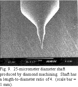
In machining, scaling has a profound effect as
previously mentioned. Conventional metal cutting correlations are based on the assumption that
the tool is extremely sharp compared to the chip
being produced. Additionally, if the component
being machined is very small, as shown in Fig. 9,
the cutting conditions such as feed, speed, tool
location, etc., must be continually monitored and
adjusted to keep from breaking the micro component. This adds another level of complexity to a
relatively simple process at the macroscale [8].
MICROMANUFACTURING APPLICATIONS
These two courses are intended to provide students with background in applications of micro
technologies. One course is relatively specialized and is taught by one faculty member. The
other course is very interdisciplinary and is taught by the students provided there is sufficient
diversity among student backgrounds.
Micro Pressure and Flow Sensors
This is a relatively specialized course currently under development. The course is intended
for
biomedical engineering and science students and addresses the design, fabrication, and
application of micro sensors. 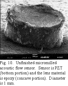 Basic
transduction principles, such as piezoelectric and
piezoresistive effects, are introduced and methods for utilizing these effects in the design of
physiological
sensors for circulatory measurements and
diagnostics is addressed. Present research is aimed at
the fabrication of acoustic flow sensors based on the
piezoelectric effect. These sensors use
micromechanically machined focusing materials to give
the sensors a higher spatial resolution. The first sensor
fabricated is shown in Fig. 10.
Research such as this finds a very quick return to the
classroom environment. This particular project has
strong undergraduate involvement and much of the
fixture design with which to fabricate the sensors was
performed by a group of undergraduate students. This
work resulted in a paper presentation by the student
group at a national conference [9].
Fundamentals of Engineering Photonics
This second applications course involves concepts from physics, materials, biomedical
disciplines, as well as several fields of engineering. Because the course is offered at the graduate
level, there is freedom to be more innovative in the course delivery. The students in the course
are divided into two groups. One group had the responsibility of devising laboratory experiences
in ray and wave optics and lasers. The second group had the responsibility to develop laboratory
experiences in measurement and communications applications using light and optical fibers.
For the first half of the course, the students designed the laboratory demonstrations while they
developed lecture and recitation modules on the course content. Each student was allowed to
select the material based on their own background and interests. For example, a doctoral student
in biomedical engineering presented the human eye as a photonic sensor and gave considerable
insight and engineering analysis into the function of the eye beyond that contained in normal
texts. This approach seemed to work very well and students were very enthusiastic. This gave
most of them their first introduction to preparing and presenting a class lecture.
The laboratory was a bit more difficult for the students. It required them to design the
experiments around available and readily purchasable items. There was a considerable design
component and they were left to acquire all materials which exposed them to acquisition
procedures within a structured environment.
RELEVANCE OF COURSE DEVELOPMENT TO
CURRICULA
The courses developed formed an emphasis in microtechnologies for a graduate degree
program
in Manufacturing Systems Engineering. The MSE program is a very interdisciplinary degree
program wherein a student will take concentration and broadening course work to provide a
broader perspective of the manufacturing enterprise. The broadening courses are from outside
the student's discipline and one course is from business or management. From within the
student's discipline, he (she) selects a series of courses focused in the area of the thesis or
practicum project. The courses in micromanufacturing provided a group from which the student
could tailor a degree program with considerable flexibility. These courses were also suitable for
students pursuing a more traditional MS degree.
Because of the interdisciplinary nature of the courses, faculty from a number of departments
collaborated on the development of the courses and laboratories. Those faculty were also
involved in undergraduate education and the microtechnologies were brought into those courses
where appropriate. Examples of integration of micromanufacturing into undergraduate course
include senior design courses (ME, BME, IE), advanced machine design (ME), machining
analysis (ME), machine vision and inspection (IE), reliability engineering (IE), and
microfabrication principles (EE).
The courses are continually evolving because of the nature of the content. This attracts
students
from many areas not directly involved in microtechnologies. The best undergraduate students
were provided the opportunities to work with the research personnel, primarily in equipment
operation and conduct of experiments. Undergraduate students routinely operated the focused
ion beam machine, micrometrology equipment, clean room equipment, and the high precision
machining cell. These undergraduate students would not otherwise have had access to
sophisticated
equipment in a more traditional research vs educational environment.
ACKNOWLEDGMENTS
Because the research and curriculum development are so closely tied, it is difficult to cite
particular contributions and support for each aspect. The work described was supported by the
National Science Foundation under grants EEC-9420600 and OSR-9550481, the State of
Louisiana under grant NSF/LEQSF(1995-98)-SI-01, the AT&T Foundation and the
AT&T
(Lucent Technologies) Shreveport Works, and the Air Force Office of Scientific Research.
REFERENCES
- M. Vasile, C. Friedrich, B. Kikkeri, and R. McElhannon, "Micron-scale machining: tool
fabrication and initial results", Precision Engineering
(119)2/3, pp.180-186, 1996.
- R. Gu, "Fabrication of microstructures by uv laser ablation", MS Thesis, Louisiana Tech
University, 1997.
- X. Huang, "Fabrication of three dimensional microstructures by uv laser-induced poly-
merization", MS Thesis, Louisiana Tech University, 1996.
- C. Friedrich and M. Vasile, "Development of the micromilling process for high-aspect-
ratio microstructures", J. MEMS, (5)1, pp.33-38,
March 1996.
- P. Coane and C. Friedrich, "Fabrication of composite x-ray masks by micromilling", in
Microlithogrpahy and Metrology in Micromachining II, Postek and Friedrich,
Editors,
Proc. SPIE 2880, pp.130-141, (1996).
- C. Friedrich and M. Vasile, "The micromilling process for high aspect ratio microstruc-
tures", Microsystem Technologies, (2)3, pp.144-148, 1996.
- C. Friedrich and S. Kang, "Micro heat exchangers fabricated by diamond
machining", Precision Engineering, (16)1,
pp.56-59, 1994.
- C. Friedrich and B. Kithiganahalli, "Deflection compensation model for the machining
of
microshafts", Proc. 1994 ASPE Annual Conf., pp .461-464.
- R. Keynton, J. Li., L. Hall, M. Tate, and C. Friedrich, "Fabrication and evaluation of
micro-acoustical lenses", presented at 1996 Annual Meeting of Biomedical Engineering
Society, Penn State Univ.
 Back to Table of
Contents
 Focused ion
beam micromachining (FIB) has been widely used in the semiconductor industry to
create very fine cross sections in electrical structures and junctions. The process uses an
accelerated beam of metal ions which impact the surface of the work material. The kinetic
energy of the ions results in atoms of the
work piece being dislodged from the surface
thus providing atomic-scale machining.
 Materials
such
as ceramics and diamond have use in high temperature or corrosive
applications and these materials must sometimes be given complex geometries. Laser
micromachining typically uses a pulsed excimer laser with a wavelength of 248nm (KrF). The
pulse width lasts tens-of-nanoseconds and the pulse rate is normally 2 kHz or less. This gives a
relatively low duty cycle which, coupled with the
short pulse width, results in little thermal damage to
the material away from the ablated region.
 Certain
polymer photoresists can be polymerized by ultraviolet radiation. This process is similar
to conventional stereo-lithography except the spot is normally smaller and the thickness of the
layer of polymer to be polymerized is thinner. In the microscale process, the laser wavelength is
typically 351 nm from a XeF excimer laser. The power of the laser must be greatly reduced so
that ablation of the resist does not take place. This process requires additional capabilities and
hardware so that after a layer of the resist is "written" by the laser with the desired pattern, the
partially solidified material is immersed in the liquid polymer and raised so the surface of the
previously written layer is just micrometers below the surface of the liquid.
 The machining
parameters for micromilling are dependent on the material being machined. For
the structure shown in Fig. 4., the spindle speed was 19000 rpm, the feed rate
was
35 um/sec
(feed of 55 nm per cutting edge), and the axial depth per pass was 4 um. The entire pattern had
a total of 35 million cubic micrometers removed and was accomplished in about 3 hours.
Although this may seem slow, it is actually a very rapid removal process for the microscale.
With these conditions, the tools did not break from static or fatigue loads.
 Micromilling
must be performed on a high precision machine tool with very smooth motions. In
such a tool, all motions should be on air bearings
with closed-loop positional control. This results in
very smooth movements, particularly at slow
speed where slip-stiction could result in tool
breakage due to a higher level of impact loading
on the cutting edges. High resolution feedback
also allows for continuous work table velocity at
slow speeds. An example of such a machine tool
is shown in Fig. 5. The milling machine is
largely composed of granite to provide vibrational
and thermal stability coupled with a large mass to
provide a low natural frequency [4-6].


 etching can
take place at the beaker-scale with a hot plate. This
course has evolved over 4 years and as new equipment
is acquired, it continues to evolve.
 The third
aspect of the course deals with processes at the microscale and how they compare or
deviate from conventional correlations. For example, at the microscale a flowing fluid may have
an extremely high Reynolds number and yet maintain laminar flow characteristics because there
is insufficient lateral dimensions in the microtube to permit eddy formation. There may also be
insufficient size to develop boundary layers thus altering heat transfer and fluid drag correlations.
In
other cases, the lack of a gradient in the fluid cross section may lead to slip-flow
conditions at the wall where there is very little
boundary layer development.
 Basic
transduction principles, such as piezoelectric and
piezoresistive effects, are introduced and methods for utilizing these effects in the design of
physiological
sensors for circulatory measurements and
diagnostics is addressed. Present research is aimed at
the fabrication of acoustic flow sensors based on the
piezoelectric effect. These sensors use
micromechanically machined focusing materials to give
the sensors a higher spatial resolution. The first sensor
fabricated is shown in Fig. 10.
 Back to Table of
Contents