In this paper, a complete set of experiments on Motor Control Laboratory are designed. The main purpose of this course is to teach the basic techniques of designing electro-mechanical systems and to gain the knowledge on tuning and controlling dynamic systems. The design of this course should attract special interests of many universities because it actually requires students to build the most expensive part of the instruments so that the instrumentation budget would fit in a reasonable amount of money. These instruments include a simple PC based spectrum analyzer, a motor driver and motor speed/position controllers. Experiments use these instruments include design of analog circuits, design of power electronic circuits and motor drives, identification of dynamic systems, and speed/position control of servo motors. All experiments are specially designed for mechanical engineering students to gain basic electrical engineering techniques, control experiences, and dynamic system instincts. The responses from the students who took this course are overwhelming. Also many industrial companies found very useful to employ students who has taken this course.
Mechanical engineers these days are different from the past. They need more knowledge in the field of Electrical Engineering and Computer Science. The work they need to do also covers electronics, programming, electric machinery, and signal processing. A course designed specifically on integrating these fields becomes very important to mechanical engineering students. We strongly feel that a laboratory that covers these fields should be designed.
The course is designed in the following procedures:
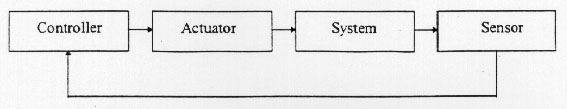
Consider a standard block diagram of motor control system in figure 1. In order to perform this experiment, we need to teach students how to design an analog circuit, how to design a motor driver, how to identify the mathematical model of a dynamic system, and how to control a dynamic system. Instruments required to complete this experiment are controller, driver, motor, sensor, sensor conditioner, power supply, function generator, spectrum analyzer and other small instruments. Students in the process of building controllers, drivers, sensor conditioners, spectrum analyzers and using these instruments to construct a control system can gain the hands on experience on designing, tuning and understanding the behavior of both component level and system level of real dynamic systems.
The course is divided into six laboratories and a final project. They are listed as follows:
| Labl - Design and Analysis of Analog Circuits | - 1 Week |
| Lab2 - Design A Linear Driver For D.C. Motors | - 2 Weeks |
| Lab3 - System Identification Of A D.C. Motor | - 2 Weeks |
| Lab4 - D.C. Motor Speed Control | - 1 Week |
| Lab5 - Decoder Design For Encoders And Linear Scales | - 1 Week |
| Lab6 - D.C. Motor Position Control | - 2 Weeks |
| Final Project: Design and Control Selected Systems | - 6 Weeks |
The contents of Lab1covers the basic OP circuits [2] including adder, multiplier, differentiator, integrator, filter and buffer. Students are required to build each components to test the bandwidth and the functionality of each circuit and the performance of different operational amplifiers. Students should be very careful about avoiding the saturation condition and unbalanced circuits. After the test of each component, students are required to build an analog circuit to simulate the behavior of a mass-spring-damper system. In the process of constructing the simulation circuits, they are required to avoid saturating op-amps during the normal operation. After this lab, students should learn the basic circuit design and tuning techniques to build an analog servo controllers.
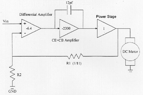
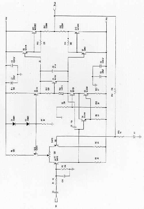
Lab2 covers the basic theory of power electronics [3]. Students are required to understand transistor, MOSFET, and SCR circuits. A linear drive for d.c. servo motors is constructed as shown in figure 2. Students should build and test the driver in three portions - the differentiation portion, the common emitter plus common base amplification portion, and the Darlinton amplification portion. The bandwidth of each portion should be very carefully designed and tested so that the entire circuit would be stable at all frequencies [1]. A pre-made circuit board along with the complete circuit design are handed out to the students in the lab. Aggressive students can further modify the circuits to either improve the frequency response or to increase the power capacity of the driver. However, most of the students will follow the circuit diagram in the handout to construct the driver. Figure 2 shows the block diagram and the circuit design of this linear drive. The cost of parts and wires for this experiment is only $20. The driver they make not only give students useful hands on experiences on power electronics, but also provide the necessary actuating device for d.c. servo motor which will be used in later labs.
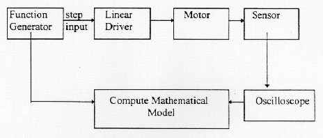
Lab3 is divided into three parts. The first part is to identify the motor mathematical model using the time domain system identification technology. Given step input from the function generator, the students are required to measure the motor velocity response, record it on the oscilloscope and compute the dynamic model in the Laplace transformation format. Driver designed in lab2 is used to complete this experiment. Figure 3 shows the experiment setup.
The second and third part of lab3 are the frequency domain system identification experiment. In the second part, students are required to build a simple spectrum analyzer from the PC 586 computer. The following programs are handed to the students:
These programs are then loaded into PC. After the carefully selected ADC/DAC/DIO board is plugged into the computer, students can then connect the system shown in Figure 4 to identify the mathematical model of d.c. servo motor. It is important to teach students how to choose a suitable ADC/DAC/DIO board. For a motor voltage to speed transfer function calculation, the system time constant varies from 0.05 sec to 0.5 sec. We taught students how the precision and bandwidth of system ID results and the speed and number of digits of the IO boards are related. Also we taught students how to select the frequency bands of the random signal to fit into the nature of this experiment.
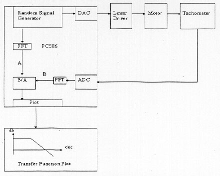
The last part of lab3 is to identify the system using frequency domain techniques. The random signal generated by the random signal generator is first sent to the driver input via the DAC port. The driver amplifies the signal and drives the motor. The angular velocity signal is taken from the tachometer and collected by the computer via the ADC port. The random signal and the velocity signal are then transformed into frequency domain using the FFT program. A transfer function plot is then shown in db-decade scale. By measuring the break frequency, students can easily find the transfer function from the motor voltage input to speed output. At the end of lab3, students are also required to compare the time domain and frequency domain identification results. They can also discuss how identification errors are related to the design of the experiments and the instrumentation.
Lab4 requires student to design a motor speed controller. They should use the result obtained from lab3 to design the controller transfer function. Students are required to do the lab in two steps- simulation and implementation. They use MATLAB or MATRIXx to do the simulation and use op-amps to construct the controller. Students are required to compare the performances between proportional and IP controllers [4]which are shown in Figure 5.
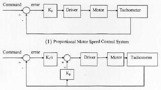
Students are required to try the proportional and IP controllers in this lab. They are also required to measure steady state error, time constant, and to watch how the driver saturation may affect the control system. Labl techniques are also pointed out again to the students to watch on the circuit balancing technology when they design the controller circuits.
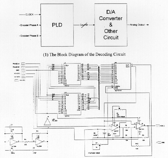
The main function of Lab5 is to prepare the sensor conditioner for motor position control. It also teaches students how to design a simple logic circuit. Instead the traditional logic gate that may create a bulky circuit board, we use PLD to construct our decoder circuit. Students are required to use ABEL program to write the decoding logic, simulate the circuit on the computer, and then burn the circuit into Lattice PLD. This procedure is very useful to those students who are not major in electrical engineering to understand how to design logic circuit using computer-aided software. Students also learn how to take the encoder outputs, put a buffer circuit after them, connect to the PLD and then send the decoded signal to a DAC to generate the analog position signal. Figure 6 shows the block diagram of the decoding circuit.
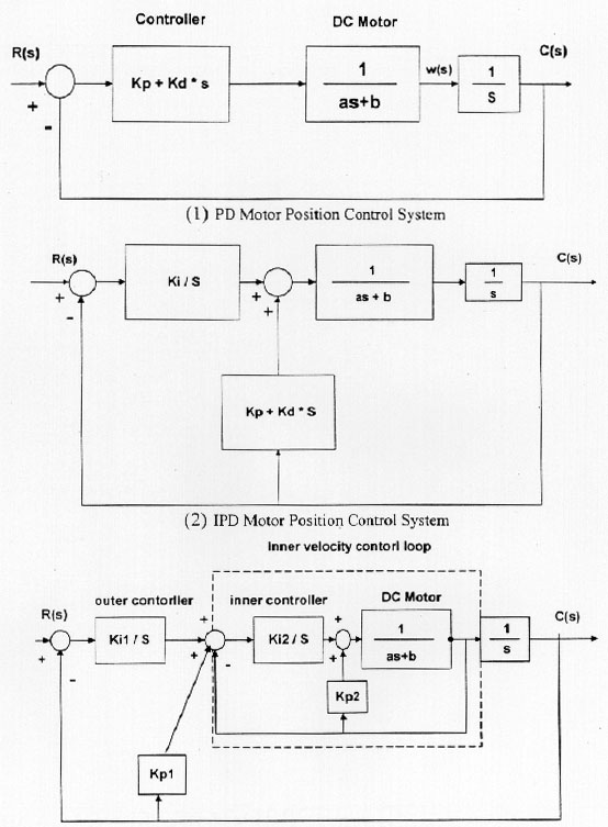
The last lab is to design a motor position controller. Students are required to test the PD, IPD and multi-loop controllers in this experiment. Figure 7 shows the block diagrams of these four controllers.
It is important to let students first build their own analog controllers, try to avoid op-amp output saturation during the control operation, and to add their own anti-windup circuits[5]. During the experiment, they can also compare the performances of all four types of controllers, learn how to tune the controller gains. We found this is extremely useful to students in the future job hunting process. Industrial companies are very happy about having an employee that has controller tuning experiences. Many students also integrate their velocity controller, decoding circuit, and different position controller into one box, and build a nice and rigorous motor controller.
At the end of this course, students are required to design controllers for various dynamic systems. They are allowed to pick any system they like and design a controller for it. Systems that have been used in the past include a.c. induction motors, d.c. brushless motors, XY tables, inverted pendulum systems, etc. The main purpose of this portion of the course is to let students have experiences to attack a problem from scratch. Students who were successful in this project are also found more confident in their future works.
In this paper, we gave the course design on motor control laboratory. Students who have taken this course should build most of the instruments themselves so that they not only save a huge budget but also learn how to design and construct basic components of a control system. The course is also mainly designed for Mechanical Engineering students to gain experiences on handling electro-mechanical systems. Many physical hard to understand behavior of dynamic systems can be easily found and understood in these experiments. Also students are required to prove all facts they have learned from the control and dynamic system text books[4][5]. Very effective learning processes can be generated. The result of this course is very good. Many students graduated are working in the related field as a project leader, and some teaching assistants of this course are currently working as technical directors of large companies.
[1] Yih-Ping Luh, "Lecture Notes On Electro-Mechanical Systems", Vol. 1- 2, Department of
Mechanical Engineering, National Taiwan University, 1992.
[2] Paul Horowitz, Winfield Hill, " The Art Of Electronics", 2nd Edition, Cambridge
University Press, 1989.
[3] Ned Mohan, Tore M. Undeland, and William P. Robbins, "Power Electronics
Converters, Applications, and
Design", 2nd Edition, John Wiley & Sons, Inc, 1995.
[4] Richard M. Phelan, "Feedback Control System", Cornell University, 1991.
[5] Gene F. Franklin, J. David Powell, and Abbas Emami-Naeini, "Feedback
Control of Dynamic Systems",
Addison-Wesley Publishing Company, l991.
 Back to Table of
Contents
Back to Table of
Contents