DEVELOPMENT OF AN INTERDISCIPLINARY
SENIOR
LABORATORY EXERCISE
ABSTRACT
This paper concerns the development of an interdisciplinary senior laboratory exercise in the School of Engineering at Western New England College. The exercise takes place in an integrated manufacturing and controls laboratory which is supported by a grant from the National Science Foundation. The laboratory was designed by a cross-departmental development team in collaboration with a local industrial entity. The exercise is described, along with the challenges faced in implementing the activity within a traditional academic environment.
INTRODUCTION
The role of engineers in American industry today is different than it was when most engineering faculty were educated. While engineers are still expected to possess traditional engineering skills, they must also have a good grasp of basic business concepts, be creative problem solvers, have the ability to perform effectively on cross-functional teams, possess excellent communication skills, and be able to adapt to a changing business environment. We believe that the most significant change facing engineering educators is exposing students to the interdisciplinary nature of engineering practice. Unfortunately, accomplishing this goal requires a concept new to most academic environments - the cooperation of engineering faculty across departments.
As engineering faculty, we typically have little or no experience working in teams, except through some prior industrial experiences. Departments typically function as independent entities with little or no interaction. In fact, competition for resources often results in bitter rivalries that conflict with the teamwork objective. The unstated goal of some academic departments may be to become a virtual empire, fortified with boundaries that cannot be penetrated. The effect of these boundaries can be devastating in terms of exposing students to interdisciplinary engineering practice. Industries have been motivated by national and international market forces to improve manufacturing effectiveness by changing their management structure to ensure better cooperation among business entities. Similar market pressures are just beginning to be felt in academia.
This paper describes an effort to change a portion of the engineering curriculum at Western New England College (WNEC). The project was accomplished by an interdisciplinary team of faculty, along with a partnership with Monsanto Corporation. We will share both the challenges faced in implementing the project as well as the technical results of the work. We hope that, while efforts such as this are relatively new to most academic environments, we all can learn and benefit from this experience. Other references to this work are given in [1]-[4].
BACKGROUND
We submitted an equipment grant proposal to the National Science Foundation (NSF) in the Fall of 1993 for the development of a new laboratory that we hoped would be innovative and progressive. At that time, we represented the three academic departments within the WNEC engineering school (industrial, electrical, and mechanical). The main goal was to create a modernized laboratory that would emulate a modern manufacturing environment and provide a state-of-the-art rapid prototyping control system platform. The proposal, entitled Development of an Integrated Manufacturing & Controls Laboratory, was accepted and funded for a three-year implementation period.
The objectives of the laboratory were stated as: (1) to provide an environment where interdisciplinary experiments can be performed, (2) to provide an opportunity for each engineering program to conduct independent experiments, (3) to provide the students with experience in the interdisciplinary nature of engineering practice, and (4) to provide a facility for the design, manufacture and testing of plastic products. From the start, we worked as an enthusiastic team, including frequent brainstorming sessions and trips to local industries. Often, personal goals were sacrificed for the good of the project. The final equipment decisions were made jointly, with numerous trips to equipment vendors and educational institutions during the proposal and implementation phases.
The input from The Plastics Division of Monsanto was critical. This partnership started informally, then grew to a more formal relationship. The key collaborations were as follows: (1) we held several brainstorming meetings when developing the proposal to determine basic laboratory configuration; (2) we exchanged visits during which scientists from Monsanto's research group conducted a series of seven one-day workshops in polymers and plastic extrusion, and faculty from WNEC gave seminars on the use of neural networks and fuzzy logic theory in the design of controllers; (3) we worked together on equipment selection after the grant was offered; and (4) we discussed activities to be initiated using the new laboratory, most importantly interdisciplinary activities to be performed across departments. The partnership also resulted in the donation of equipment to WNEC, such as a small research injection molding machine and peripherals.
LABORATORY FACILITY
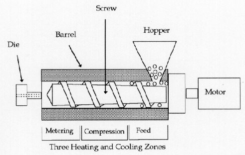
The laboratory is centered around a ¾ inch extruder, water trough, and combination puller/pellitizer. Figure 1 is a schematic diagram of the extruder. The system also includes dies to produce rods and strips. The extrusion process was chosen because it is a safe and affordable process with suitable complexity from a manufacturing and controls viewpoint. For example, several process parameters must be set, including three barrel zone temperatures (feed, compression, metering), die temperature, extruder screw speed, puller speed, and die opening width. The output of the process can be evaluated in two ways. First, process variables that are not directly controlled, such as melt temperature and pressure, can be measured and analyzed. Second, properties of the finished product, such as strength, toughness, and dimensions, can be measured and analyzed. Another advantage of the extrusion process is that control systems can be implemented with minor changes to the equipment.
Figure 1: Schematic Diagram of Extruder
The extruder is optionally controlled using a fast DSP board with: (1) Cockpit software which allows on-line interaction and modification of control algorithm parameters running on the DSP board; (2) trace software which is used for data acquisition and display of sensor signals and control variables; and (3) a C code generator which is required for automatic implementation of the control module generated using SIMULINK. This configuration allows for rapid prototyping, which is an integral part of any successful real-time control assignment, since students must be able to finish the project within a reasonable amount of time. The laboratory equipment will allow students to implement and test a variety of control algorithms. This will make possible rapid prototyping in the design and implementation of controllers using high-level languages, avoiding time-consuming low-level programming and debugging and/or in-depth knowledge of PC-hardware interrupts.
INTERDISCIPLINARY SENIOR LABORATORY EXERCISE
At WNEC, engineering students in all majors take a series of three two-credit laboratory courses during their junior and senior years. The interdisciplinary activity takes place during the third laboratory course. Prior to this activity, students in all majors would have performed independent exercises to learn basics of extrusion (mechanical & industrial engineering), quality control for plastics (industrial engineering), and control systems (electrical engineering). These previous activities are designed to: (1) help students understand key concepts in manufacturing and controls, and (2) prepare students for the interdisciplinary activity. These exercises are described in more detail in [2] & [3].
The goal of the five-week interdisciplinary laboratory exercise is to design an economical control system for manufacturing plastic straps to meet customer strength requirements (see Figure 2). The components of this activity include: (1) experiments to design tolerances for each temperature zone, where customer-driven dimensional tolerances are translated to process-driven controller tolerances using design of experiments (DOE) methodology; (2) experiments to design alternative controllers, where proportional, PI (proportional-integral), and PID (proportion-integral-derivative) controllers are explored and control parameters are optimized; and (3) experiments to make product using the several potential control systems and determine the option that best meets tolerance requirements at an economical price.
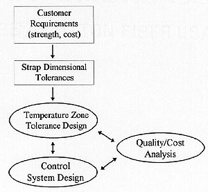
Figure 2: Conceptual Framework for Laboratory Activity up
This activity gives students experience in balancing the cost of tight control versus the control necessary for achieving product quality goals. Students work as a concurrent engineering team, communicating using meetings and memoranda. In many traditional industrial environments, the three components are performed in series. For example, mechanical engineers may do the tolerance design, electrical engineers the control system design, and industrial engineers the quality versus cost analysis. This serial methodology causes long lead times due mainly to the inability to anticipate problems when making isolated design decisions. Another characteristic of the activity is that many alternative solutions exist. And, teams must make decisions based on technical issues as well as business issues. The remainder of this section details the three types of experiments performed by the students. Note that while they are presented as three separate groups of sub-activities, the laboratory exercise is designed so that they are performed concurrently.
Tolerance Design
Tolerances for the four key temperature parameters (barrel feed zone, barrel compression zone, barrel metering zone, and die) are determined as follows: (1) a factorial experimental design is used to analyze the effects of the four factors on plastic strap dimensions, as well as potential interactions among the factors, (2) plastic strap are made according to the experimental design, (3) those factors and interactions that have a significant effect on plastic strap dimensions are determined statistically, and (4) the plots of significant effects are used to determine temperature tolerances for the given strap dimensional tolerances. The students make all key decisions, including the low & high levels at which to set temperatures, and the constant levels at which to hold other operating parameters. The lack of direct control by the instructor often results in unanticipated results, due to the random nature of the output. However, this does not compromise the activity's effectiveness.
The results of one group are described below. This group found a significant interaction of two temperature zones, resulting in a graph similar to Figure 3. Their conclusion was that if the feed zone temperature was kept at 400 degrees, then little control was needed over the compression zone temperature.
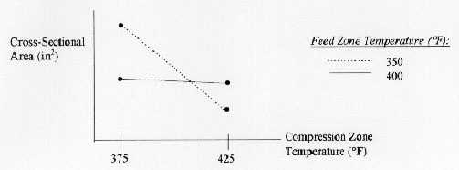
Figure 3: Interaction Effect on Strap Dimensions up
This group also found that the die temperature had a significant effect on strap dimensions. They consulted the main effect plot (Figure 4) and used the slope of this line to determine tolerances on temperature zones given certain strength tolerances.
PID Controller Design
Students design a variety of controllers, such as Proportional, PI (Proportional-Integral), and PID (Proportion-Integral-Derivative), to meet the required temperature tolerances. PID design consists of adjusting the proportional gain kp, the integral gain ki, and the derivative gain kd, as shown in Figure 5. PID controllers are used extensively in industrial processes. For example, manufacturing processes often have built-in PID controllers that require periodic parameter adjustment and re-design.
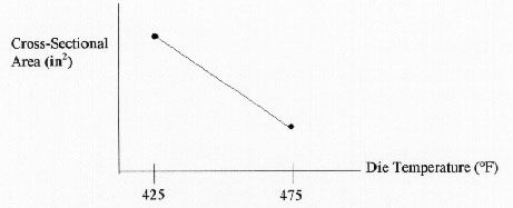
Figure 4: Main Effect on Strap Dimensions up
Figure 5: PID Regulator up
Sophisticated methods exist for designing PID controllers to satisfy a given steady state and transient response characteristic and a required disturbance rejection and input tracking. These design methods are based on complete knowledge of the system dynamics. However, World War II triggered initiatives for scientists to develop methods relying on experimental data with quick design cycles. J.G. Ziegler and N.B. Nichols (1942-1943) developed a method to calculate the PID feedback gains using the parameters obtained from the experimental step response of the system. Their method consists of increasing the proportional feedback gain, with the derivative and integral gains set to zero, until a sustained oscillation is observed in the step response of the system as illustrated in Figure 6. The period of the oscillation is then determined from this graph. Finally, the period of oscillation and the corresponding proportional gain are used to calculate the PID gains using a table lookup. The experimental Zeigler-Nichols design method is also appropriate given the lack of background of all students involved in the activity.
Figure 7 illustrates the hardware setup for this exercise. The buffer amplifier circuits are constructed by the students and they learn to operate a DT2811 data acquisition board along with a digital oscilloscope program to record the step response of the system. They learn how to collect, and port data from the digital oscilloscope to the MATLAB software. Then MATLAB is used for data manipulation and computation of statistical properties of the steady state response of the system.
Figure 6: Period of Oscillation up
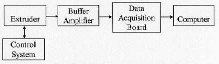
Figure 7: Hardware Setup up
Quality-Economic Analysis
The students run the extruder using the various controllers to analyze their ability to consistently meet dimensional tolerances. Specifically, they run the extruder using the default PID control parameters, while determining the oscillation cycle time for each extruder temperature controller, then they run the extruder using only the P control parameter, while determining the oscillation cycle time for each extruder temperature controller. Finally, they run the extruder using a P control parameter that is ½ the default setting. This latter run is meant to simulate the lack of a sophisticated control system. It is not surprising, given the robust nature of the parts manufactured, that a sophisticated control system is probably not necessary for this application.
IMPLEMENTATION
The technical challenges of the project were successfully met, even though at times some creative problem solving was necessary. The most fulfilling aspect of the project was our interaction with the scientists and engineers from the Plastics Division of Monsanto. We believe that our relationship developed into a mutually-beneficial partnership; the project would not have been as successful without their help. This partnership, as well as other less formal relationships with which we have been involved, illustrate the interest that practicing scientists and engineers have in undergraduate education. They continue to bring enthusiasm, energy, and perspective to WNEC.
The implementation of this project did, however, necessitate breaking new ground in the areas of facility management, finance, and scheduling. The main challenges related to the existing departmental-based organization. At WNEC, departments are: (1) assigned laboratory space, (2) allocated equipment and supply budgets, and (3) allowed to schedule laboratory meeting times independently of other departments. These challenges are described in detail below.
The first main challenge concerned choosing the physical location of the laboratory. We knew that the location chosen would be one that previously belonged to a specific department, and hence we were concerned about how this decision would be perceived by other faculty members. When a decision was finally made, we were careful to communicate with faculty members who were affected by the decision. A related issue involves maintenance of the laboratory. Since all supporting staff (e.g., technicians, machinists) are assigned to departments, it was unclear who would be responsible for keeping the facility clean, maintaining equipment, purchasing supplies, and monitoring the laboratory's use. We continue to take the main responsibility in this area, even though we have an understanding with certain support personnel that they must provide assistance if requested.
The second main challenge concerns finance. This grant is a matching proposal and the three departments agreed to contribute their share of the funds. Ongoing funding was not discussed until after the grant was accepted. While in retrospect, we would have made appropriate arrangements in advance, we have not had trouble obtaining funding as needed.
The third, and perhaps most difficult challenge, concerns scheduling. The laboratory must be scheduled so that the interdisciplinary exercise allows for students from different departments to meet jointly. Similarly, the laboratory must be available for each department to perform pre-requisite laboratory exercises at separate times. We worked together with the department heads to make this possible. In the future, the use of a shared laboratory must be accounted for in the schedules. Perhaps one block of time will be reserved for the senior laboratory course for all majors. In a related issue, the incorporation of an interdisciplinary exercise has also necessitated the three majors to organize their senior laboratory course in similar ways, in terms of the length of each exercise and the number of students on a team. The solution of this problem, like all others, required creativity, but was successfully managed.
CONCLUSION
Ultimately, academia should learn from industry and adopt the concept of teamwork. Our interdisciplinary team, working together with industry, developed a laboratory activity that is consistent with a design-manufacturing problem faced in the real world. The new laboratory has become the most used in the engineering school. The implementation of the interdisciplinary activity has necessitated the breaking down of traditional departmental barriers, but was successfully accomplished.
ACKNOWLEDGMENTS
The development of the Integrated Manufacturing and Controls Laboratory was funded through NSF Equipment Grant DUE-9451342. The following individuals from The Plastics Division of Monsanto Corporation, Indian Orchard, Massachusetts, contributed to this effort: Dr. L.S. Spangler, Dr. J.S. Royal, Dr. R.L. Kruse, Dr. O. Chang, Dr. R. Wong, Dr. B. David, Dr. T. Ray-Chaudhuri, Dr. L.A. Goettler, and Mr. O.J. Roberts.
REFERENCES
1. Rahnamai, K.R., and Gorman, K.J., "Real-Time Data Acquisition and Controls Using MATLAB", Proceedings of the ASME Computers In Engineering Conference, Boston, Massachusetts, USA, September 13-17, 1995.
2. Rahnamai, K.R., Maleyeff, J., Farris, J.P, and Spangler, L.S., "Development of an Integrated Manufacturing & Controls Laboratory", Proceedings of the International Conference on Education in Manufacturing, San Diego, California, USA, March 13-15 1996.
3. Rahnamai, K.R., Maleyeff, J., and Farris, J.P, "Implementation of an Integrated Manufacturing & Controls Laboratory", Proceedings of the 1996 ASEE Annual Conference & Exposition, Washington, DC, USA, June 23-26 1996 (including poster presented at NSF-Sponsored Undergraduate Instrumentation and Laboratory Improvement Program).
4. Rahnamai, K.R., and Gorman, K.J., "Rapid Prototyping of Fuzzy Logic Controllers", Proceedings of the ASME Computers In Engineering Conference, Irvine, CA, USA August 18-22, 1996.
 Back to Table of
Contents
Back to Table of
Contents