 (1)
(1)LIMITATIONS OF FEEDBACK AMPLIFIERS ANALYSIS
BASED ON TWO PORT NETWORK MODELING
ABSTRACT
On this paper, the limitations and applicable range of the traditional method of analysis of feedback transistor amplifiers for calculating the transfer function using the relationship a/(1+af) in comparison to the application of Kirchhoff method is presented. A brief description of the traditional method of analysis and their assumptions is given. One example is presented where the assumptions are met and identical results are obtained applying the traditional method and the Kirchhoff one. A second example is given where even though the assumptions are not met, the traditional method is applied and the result is compared to the Kirchhoff method, indicating the error degree on the gain amplifier and the input resistance.
INTRODUCTION
The general method used today for the analysis of feedback amplifier circuits is based in the computation of the total feedback circuit transfer function, given by equation a/(1 + af), the general equation of feedback control systems. We have to compute "a" and "f" expressions separately and then substitute their values in the general expression. It is important to remark that transfer functions "a" and "f" have to be mutually independent. For that, it is used the most general circuit representation: a two-port network. That restricts the problem to the interconnection of 2 two-port networks, circuits "a" and "f ", corresponding to the basic amplifier and the feedback network respectively. These transfer functions are mutually dependent and that do not permit to use them in the general expression a(1+af). Thus, it is necessary to transform such circuits in some "new" configurations. In that way, we will be able to apply the methodology using the generalized transfer function.
This method is based in the manipulation of the parameters of two port networks of the basic amplifier and the feedback network, in such a way that it constitutes a "new" circuit "a", starting with the original basic amplifier and adding to it the effects of the signal generator the load of the feedback amplifier. In the same way the formation of the "new" circuit "f" use the components of the two-port network that represents the feedback network. That is, in general, the procedure used by the experts for the analysis of feedback amplifiers.
The limitations that exists in this kind of feedback circuit analysis rests in two main points. The first one is that not necessarily the basic amplifier is a two-port network, such as happen on discrete amplifiers that compare voltage on the input or sample current on the output. The second point is that being the basic amplifier and the feedback network two-port networks, their interconnection alters, in some cases, the parameters of the networks as it is shown by Brune's Tests. For these reasons, the method is not valid for all the feedback amplifier cases.
This paper tries to show the extent of the method, its limitations and the range where it can be used even though the rules they are based are violated.
DEFINITION OF NEGATIVE FEEDBACK
Starting with the feedback amplifier signal-flow diagram shown in Figure 1, we have the following expressions
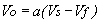
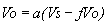
(1)if the feedback network and the load RL are not loading the basic amplifier.
 (2)
(2)
if the basic amplifier and the input are not loading the feedback network
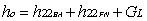
 (3)
(3)
 (4)
(4)
Equation (4) constitutes the basic equation of feedback systems
It is important to remark that transfer functions "a" and "f" can be computed inside the feedback circuit or taking out of the system, the basic amplifier and feedback network, to compute their transfer functions "a" and "f".
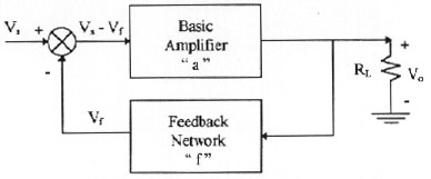
Figure 1: Feedback amplifier. Signal-flow diagram
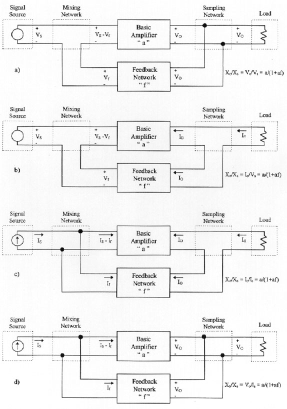
CONNECTION POSSIBILITIES (TOPOLOGIES) IN FEEDBACK SYSTEMS
Figure 2 shows a feedback amplifier block diagram that includes all its components, as well as all input and output variables. In general, the expressions that relate such variables are the following:
 (5)
(5)
 (6)
(6)

 (7)
(7) (8)
(8)
that is considering that "a" and "f" are not loading each other and in addition the signal generator and the load are not having influence on Xf and X0.
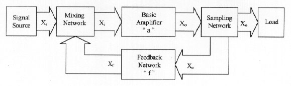
Since the most used electric variables ( Xs, Xi, Xo and Xf ) are voltage ( v ) and current ( i ), the mixing network only has two possibilities to be constructed, that is, as a node or as a mesh. Similarly the sampling network, with the conditions imposed in Figure 2, only may be also a node or a mesh. Thus, we get four possible basic configurations for feedback systems, such as shown in Figure 3.
SERIES-SHUNT TOPOLOGY
While we ignore the mutual load between the basic amplifier (BA) and the feedback network (FN), it will be possible to identify clearly on a feedback circuit, BA and FN, as we have done on Figure 3. However, it is not possible to do that in a general way due to, for example, FN and the load determine the X0 value through the expression a(Xs - Xf). Same way, if we wish to use expression (7) we have to rearrange the circuits so that will find new "a" and "f" circuits, where their transfer functions will be mutually independent.
We are going to develop a method to analyze feedback circuit topologies such as shown on Figure 3a. For that case, we are going to use the most general method of representation of circuit structures, such as BA and FN: a two-port network. That condition imposes certain restrictions to the method, since not always, a four terminal network, such as BA and FN, is a two-port network.
Two-port network model method of analysis
a) Generalizing the analysis, we will utilize two-port networks for each block (BA and
FN).
b) We will compute the transfer function Xo / Xs =
Vo / Vs using Kirchhoff's laws
c) We will give to this result the form a / (1+af).
d) By inspection we will determine who are "a" and "f" and what is their meaning relative to
the
parameters of BA and FN.
e) It will be checked out if the new circuits "a" and "f " are mutually independent and if they
comply with all the conditions imposed on the general equation: a(1+af).
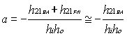
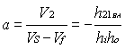
The most correct two-port network structure for solving the circuit in Figure 3a, is the one whose input parameters are connected in series and the output ones are connected in parallel. That lead us to use h-parameters to represent two-port networks BA and FN. If on Figure 3a we use such parameters, we will obtain what we shown in Figure 4. If we want to find the transfer function Xo / Xs = Vo / Vs using Kirchhoff's laws, we will get the following
 (9)
(9) (10)
(10)Combining (9) y (10), and considering that Vo = V2, we get:
 (11)
(11)
The most correct two-port network structure for solving the circuit in Figure 3a, is the one whose input parameters are connected in series and the output ones are connected in parallel. That lead us to use h-parameters to represent two-port networks BA and FN. If on Figure 3a we use such parameters, we will obtain what we shown in Figure 4. If we want to find the transfer function Xo / Xs = Vo / Vs using Kirchhoff's laws, we will get the following
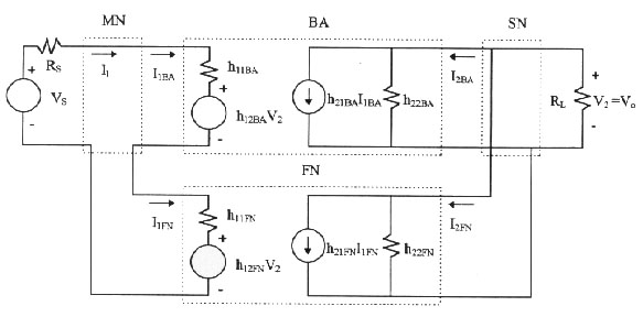
 (9)
(9) (10)
(10)Combining (9) y (10), and considering that Vo = V2, we get:
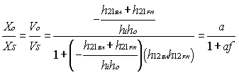 (11)
(11)where
 (12)
(12) (13)
(13)From equation (11)
 if
if
 (14)
(14)condition that restricts that forward signal transmission occurs only through "a".
Similarly
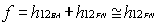 if
if  (15)
(15)condition that restricts that backward signal transmission occurs only through "f".
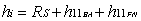
To be able to write the equations (9) and (10), we have to guarantee that I1 = I1BA = I1FN in the circuit of Figure 4, and the current that goes in BA output port, I2BA, is the same that goes out, and the one that goes in FN input port, I2FN.is the same that goes out. To be able to secure those situations, we have to use Brune's Tests. They can be seen in Figure 5 for the interconnection of two two-port networks (BA and FN) joined in series on the input and in parallel on the output, such as is the case in figures 3a and 4.
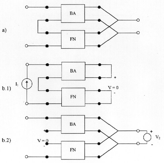
Figure 5: Series-shunt configuration and Brune´s tests up
a) Series-shunt configuration
b.1), b.2) Brune´s tests. V have to be equal to zero to interconnect correctly
BA and FN
If in a particular circuit with a series-shunt interconnection, such as shown in Figure 5a, we make the tests shown in figures 5b.1 and 5b.2, finding that V 0 at least in one case, that is more than sufficient for saying that equations (9) and ( 10) have no support and therefore equations (14) and (15) are also invalid.
If we rearrange the circuit in Figure 4 as a function of equations (14) and (15), we obtain the circuit in Figure 6, where we can verify that
 y
y 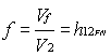
as it was established in equations (14) and (15)
Also based on Figure 6, we are able to obtain "a" input impedance
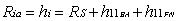 (16)
(16)and its output admitance
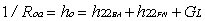 (17)
(17)Thus, it is possible to prove that the input impedance and output admitance of the feedback amplifier, have the following expressions
 (18)
(18) (19)
(19)USES AND LIMITATIONS OF THE METHOD
Case 1
We are going to compute Vo/Vs in the circuit of Figure 7, using the method described in section 3.1. To use that method, we first have to determine if BA and FN are two-port networks as a necessary condition. In fact, Figure 8 shows that BA and FN are two-port networks. The sufficiency condition, Brune's test, is applied in Figure 9, using the method shown in Figures 5b.1 and 5b.2. It is evident in Figure 9 that we obtain V= 0 in both cases. That permit us to use the results that we got in equations (14) and ( 15). Then, applying the method outline in figure 6, we obtain Figure 10.
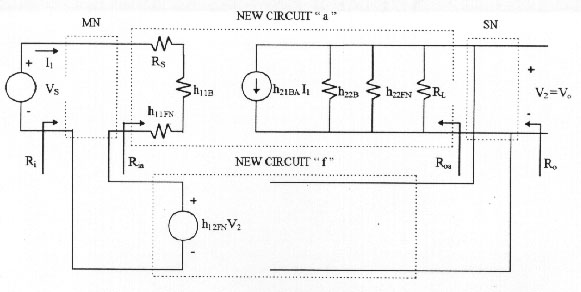
Figure 6: Feedback amplifier rearranged. up
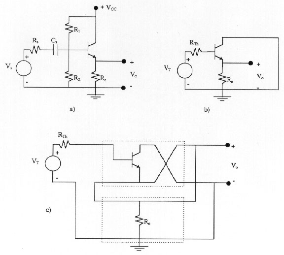
Figure 7: a) Amplifier circuit
b) Small-signal amplifier circuit. Vth =(Rb
/ (Rb+Rs))Vs , RTh =
Rb
// Rs , Rb = R1 // R2
c) Circuit of b) redrawn to apply the method up
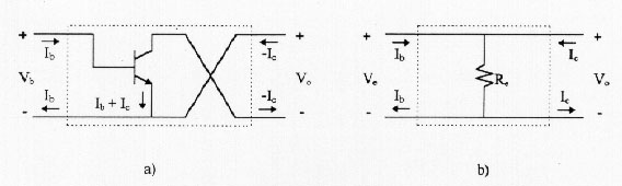
Figure 8: a) Two-port representation of the basic amplifier
b) Two-port representation of the feedback network up
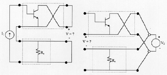
Figure 9: Brune´s tests of the series-shunt configuration using the two-port networks of Figure 8, where it is verified that V = 0. up
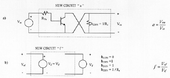
Figure 10: a) Circuit for computing " a "
b) Circuit for computing " f " up
After solving the circuits in figures 10a and 10b, and using the results obtained in equation (8), we can show that we are able to get the same result if we solve the circuit in Figure 7b using the general resolution method (Kirchhoff.'s laws).
Case 2
We are going to use the same method described in the section 3, to compute Vo / Vs in the circuit shown in Figure 11.
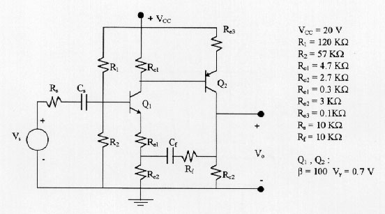
Figure 11: Amplifier circuit
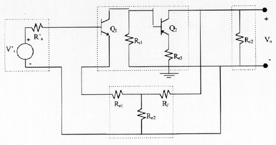
Using the previous procedure, we prove first that BA and FN are two-port networks. For that purpose both circuits are shown in Figure 13. Since Figure 13a shows that the current that goes in is different from the one that goes out for both the input and output port. Thus, BA is not a two-port network and it is not correct to apply the method. Still, if we obviate this requirement, we can also check that Brune's tests fail as it is shown in Figure 14, where we can verify that in both cases V 0.
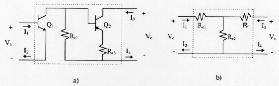
Figure 13: a) Two-port representation of the basic amplifier where it is verified
that, it not a two-port network: I1 I2 ; I3
I4
b) Two-port representation of the feedback network up
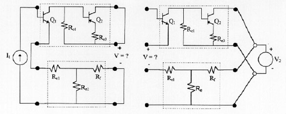
Figure 14: Brune´s test of the series-shunt configuration using the two-port networks of Figure 13, where it is verified that V 0. up
If after these two results, you still insist on solving this problem using the feedback technique, we are going to show some results showing that the error made when the amplifier voltage gain and input resistance is computed using the simplified method for feedback systems, in comparison when we compute them using Kirchhoff's laws. These results are shown in Figures 15 and 16, and they were computed using PSPICE circuit simulator, using the h-parameters model. Figure 15 and 16 show the results using Re3 = 0,1 K and Re3 = 0.
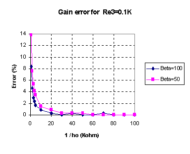
Figure 15.a: Gain error as a function of the transistor output resistance (1/ho), for beta = 50 and 100
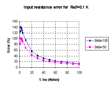
Figure 15.b: Input resistance error as a function of the transistor output resistance (1/ho) for beta = 50 and 100. up
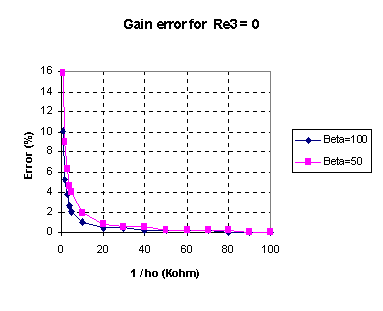
Figure 16.a: Gain error as a function of the transistor output resistance (1/ho), for beta = 50 and 100.
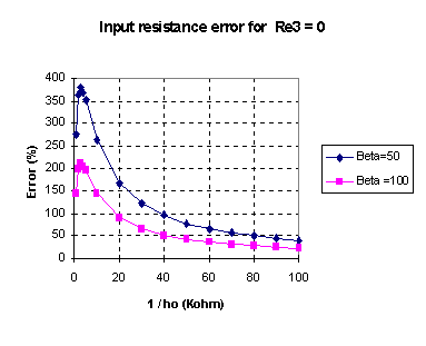
Figure 16.b: Input resistance error as a function of the transistor output resistance (1/ho), for beta = 50 and 100.up
CONCLUSIONS
As we can notice, the error made in computing Vo / Vs gain using feedback techniques, is very small when the transistors output resistance (1/ho) from network BA is bigger that 40 KW. That corresponds to transistors used normally in solid state circuits.
On the other hand, the computation error upon using this method for the computation of the feedback circuit input resistance, Ri, is highly evident . It can reach up to 380% for low values of transistor output resistance and beta = 50. For the circuit in Figure 11 and typical values of 1/ho the error can oscillate between 20% and 100%, for beta between 50 and 100.
Our results also show that the presence of Re3 in the circuit of Figure 11, produce smaller errors when computing gain and input resistance.
Finally, those results show clearly that feedback circuits analysis method is not always a correct method for computing circuits "a " and "f", as it is usually done in control system theory.
REFERENCES
Gray P. E., Searle C. L., "Principios de Electrónica - Electrónica física, modelos y circuitos electrónicos", Edit. Reverté, S.A., 1973.
Gray P. R., Meyer R. G., "Análisis y Diseño de Circuitos Integrados Analógicos", Edit. Prentice Hall Hispanoamericana, S.A., 1993.
Guillemin E. A., "Introduccción a la teoría de los circuitos", Edit. Reverté, S.A., 1959.
Holt C. A., "Electronics Circuits - Digital and Analog", Edit. John Wiley & Sons, 1978.
Hurst P. J., "Exact Simulation of Feedback Circuit Parameters", IEEE Trans. on Circuits and Systems, Vol 38, No. 11, pp. 1382-1389, noviembre 1991.
Ruston & Bordogna, "Electric Networks: Functions, Filters, Analysis", Edit. Mc Graw Hill, 1966.
Sedra S. S., Smith K. C., Microelectronic Circuits", Saunders College Publishers, 1991.
 Back to Table of
Contents
Back to Table of
Contents